You are using an out of date browser. It may not display this or other websites correctly.
You should upgrade or use an alternative browser.
You should upgrade or use an alternative browser.
Federal Signal Federal Signal Beacon Ray 174 Wiring Diagram
- Thread starter Chri$
- Start date
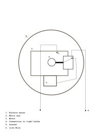
I don't remember if the 174 has the R and W connections like the 175 does. These ground to frame, and that is done by the bulb cage connecting to the drive shaft. + hot comes from the brushes on the bottom of the bulb cage that make contact with a copper plate that is seperated from grounding out.
My 174 has a single positive terminal as do the images I have of other 174's. I would not say that all 174's have a single terminal as Federal Signal would custom build their lights for special orders, but I think it is safe to say that the majority of 174's would have had a single terminal.

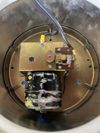
100% correct (even showing how I ground to the gear box cover). What you have labeled “4. Connection to light bulbs” is how the power is transmitted to the bulbs. Inside the bulb cage is a solid wire rod inside an insulated tube (like a hard cardboard) that terminates at the top of the bulb cage with a nut and insulated washer where the bulbs power wires attach.
FYI, the dark “circle” to the left of “4.” Is the oscillator shaft…a quick way to quickly ID a 174 (they may not be dark like mine, a 1958 vintage).
Here’s the link to my post with video:
Thread '174 Gear Works'
https://elightbars.org/forums/threads/174-gear-works.90888/
Last edited:

