Help needed in wiring Code 3 PSE AS-8 LightStik

Fireguy51

New Member
Mar 26, 2023
4
Cedar Flat, Oregon
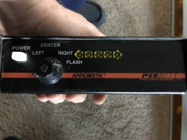
I bought a Public Safety Equipment AS-8 ArrowStik and controller, and thought I could figure out how to wire it up. I was wrong.

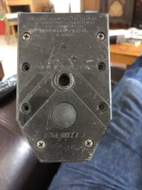
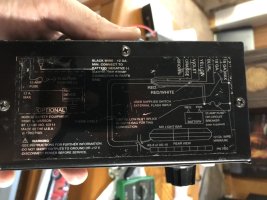
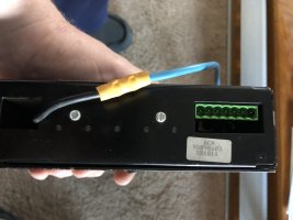
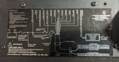
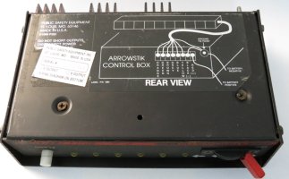
The plug on the back of the controller has 7 inputs, plus a single ground wire; it's looking for wires colored Brown, Orange, Violet, Yellow, Blue, and 2 that just say "18 gauge max."

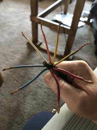
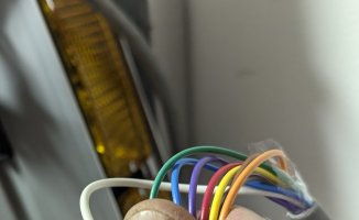
However, the arrowstik has 8 wires, plus a heavy black ground wire. It has wires colored White, Orange, Yellow, Yellow/Black, Red, Red/Black, Blue, Blue/Black, and a heavier Black wire.

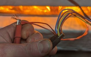
I took the arrowstik apart, traced the wires, and got even more confused. Looking from Left to Right, the Blue wire goes to pod 1, Yellow to pod 2 & 3, White to pod 4 & 5, Orange to pod 6 & 7, Yellow/Black to pod 8, Red & Red/Black going to what appears to be a ground (both wires affixed to the metal rail that all the pods attach to), and I couldn't see where the Yellow or Blue/Black wires attach to anything. The heavy Black ground wire makes it in to the lights, but is cut flush before it connects to anything.

When I connect a 12 volt source to the Red & Red/Black wires, and then to either the Blue or Yellow/Black wires, the corresponding end lights light up. But when I do the same for the Yellow, White, or Orange wires, nothing happens.

I'm kind-of stuck, and I'm not sure what to do next. Does anyone know? I'll include some pictures of what I have.

Thanks!

Fireguy51
 

Attachments

  • IMG_7289.jpg
    IMG_7289.jpg
    112.5 KB · Views: 21
  • IMG_7293.jpg
    IMG_7293.jpg
    98.2 KB · Views: 24
  • IMG_7294.jpg
    IMG_7294.jpg
    134.1 KB · Views: 28
  • IMG_7295.jpg
    IMG_7295.jpg
    92.7 KB · Views: 18
  • IMG_7296.jpg
    IMG_7296.jpg
    101.4 KB · Views: 14

shues

Lifetime VIP Donor
May 21, 2010
10,292
NW Indiana
I believe you have an older, positive-side switched ArrowStik. The ArrowStik controller you have is for a newer, ground-side switched ArrowStik. The correct controller for your ArrowStik looks like this:

The earlier version of the Arrowstik controller has 6 outlets and is positiv switched.
Rev.1:
arrowstik-control-box-1-rev1-04b-jpg.210299


Rev.2/3:
arrowstik-control-box-2-rev3-01b-jpg.210300


arrowstik-control-box-2-rev3-03a-jpg.210301


In addition to the front panel, the flash warning pattern also changed
as-pattern-jpg.210303
 
May 21, 2010
1,267
Minnesota
I might be reading it wrong but am confused. You say the yellow goes to 2/3 but nothing happens when you power it?

Bench test it with out the controller. Put power to the 2 larger wires and individually ground the other wires to see what lights up.

If that is the controller that came with it, the ends should have their own wire while the remaining 6 heads should come on in pairs. It's possible that you have a burned out bulb too.

Give that a try and post the results. The large black should not be used.
You will eventually need the green plug to connect to the control box but don't use that for this testing.
 

Tango7

Member
Jul 7, 2020
187
Chicago Metro Area
Possibly - Large Red = +12vdc, Large Black = -12vdc/ground?

Found this for the AS-10:

Wiring directions for AS6FL (9 wire cable)
The AS6FL 9 wire cable has different wire colors than the standard Arrowstik. The six center lamps
are used as an ArrowStik
The red wire goes to the passenger side outboard lamp and the red/black wire goes to the driver side outboard lamp. Connect these wires to the 700 flasher according to the flasher wiring instructions below.
Note that terminal D is connected to Ground. Connect the black wire of the cable to the +12 VDC (positive) side of the battery through a user supplied 20 amp fuse or circuit breaker. If the black wire is terminated at the controller, use a 12 gauge wire and heavy duty connector to connect the wires. Use the following chart to correctly wire the remaining wires to the ArrowStik control head.

Operations​

The different signaling modes are controlled by the rotary switch on the control head. Changing the rotary switch controls the signal direction. The ArrowStik face plate is shown in Figure 8.
The light emitting diodes (LED) on the control head indicate the signal pattern of the ArrowStik lighthead. If the Arrowstik® is not functioning correctly, refer to the TROUBLE SHOOTING GUIDE for assistance.
NOTE:
In the Left Arrow mode, the right most lamp and LED will not light.
In the Right Arrow mode, the left most lamp and LED will not light
while the two outboard lamps are connected to a 700 alternating flasher.
Standard Arrowstik...........AS6FL 9 Wire
Cable......................................Cable
Brown.....................................Yellow/Black
Orange..................................Orange
Violet.....................................White
Yellow.....................................Yellow
Blue..........................................Blue
FIGURE 8................................Blue/Black-not used
 
Last edited:

JohnMarcson

Administrator
May 7, 2010
10,971
Northwest Ohio
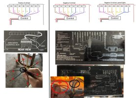
Code 3 had multiple ways they setup arrow bars. Some have a single positive to all the lamps and the colored wires ground them. Some are the opposite with the lights all grounded and the wires powering them. There are also grouped bars where you had lamps grouped together so there were less output wires. Usually the color of the larger wire(s) is the key. Large black means positive switching, large or multiple red means negative.


swi.jpg


Here is my Code 3 AS series arrow and the control schematic. The power input is the two red wires and the control grounds the colored wires.

PXL_20230330_185119767.jpg
PXL_20230330_185658808.jpg

The large black wire in yours leads me to believe you have version where the lamps are all grounded and the controller is supposed to supply power to the colored wires.

While your controller is different, it still powers the bar via two red wires and ground the lamps to activate them. Both our controllers warn to use large gauge wire to ground the controller. That is because the the controller is grounding the lights to activate them.

Long story short everything points to your bar being the warning model that has one large common ground and a positive wire for each light. This wiring method was mostly used in bars that were meant to be warning bars not arrows, although there were some arrows wired this way.

This type of controller was used, the colors aren't really important, only that it is switching the light via positive switching.

ArrowStik Control Box #2 (Rev3) -03a.jpg

I would ground the big black wire and put 12V+ to the others one at a time.
 
Last edited:
May 21, 2010
1,267
Minnesota
Code 3 had multiple ways they setup arrow bars. Some have a single positive to all the lamps and the colored wires ground them. Some are the opposite with the lights all grounded and the wires powering them. There are also grouped bars where you had lamps grouped together so there were less output wires.

Here is my Code 3 AS series arrow and the control schematic. The power input is the two red wires and the control grounds the colored wires.

View attachment 243587
View attachment 243586

The large black wire in yours leads me to believe you have version where the lamps are all grounded and the controller is supposed to supply power to the colored wires.

While your controller is different, it still powers the bar via two red wires and ground the lamps to activate them. Both our controllers warn to use large gauge wire to ground the controller. That is because the the controller is grounding the lights to activate them.

Long story short everything points to your bar being the warning model that has one large common ground and a positive wire for each light. This wiring method was mostly used in bars that were meant to be warning bars not arrows, although there were some arrows wired this way.

This type of controller was used, the colors aren't really important, only that it is switching the light via positive switching.

View attachment 243588

I would ground the big black wire and put 12V+ to the others one at a time.
A lot of arrows are electricity insulated from the frame (as I suspect this one is). If that is the case and the light is halogen then it does not matter what way the power flows. The common wire(s) can be positive or ground, same with the individual wires. In reading the OP, this stick appears to be set up like a standard 8 lamp in an MX (3 pairs with single ends) but having unused wires. I presume the abnormality in original testing was due to power backflow of improper ground/electrical path.
 
  • Like
Reactions: JohnMarcson

JohnMarcson

Administrator
May 7, 2010
10,971
Northwest Ohio
A lot of arrows are electricity insulated from the frame (as I suspect this one is). If that is the case and the light is halogen then it does not matter what way the power flows. The common wire(s) can be positive or ground, same with the individual wires. In reading the OP, this stick appears to be set up like a standard 8 lamp in an MX (3 pairs with single ends) but having unused wires. I presume the abnormality in original testing was due to power backflow of improper ground/electrical path.

This is a good point. My Whelen arrow bar has one big white wire and colored wires for the switching. Everything is shielded, you could switch it either way (and I have).
scarenot.jpg


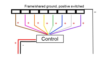
However...... There was a sinister variation of the positive switched arrow at one point, I beleive Code 3 used it in the MX. It looks a bit like this (except the MX was grouped.
shared.png

This frame grounding let them treat the arrow like any other lower deck light. I think this carried over into the AS series using the metal frame and metal reflectors as grounds, at least for a while.
 
Last edited:

Fireguy51

New Member
Mar 26, 2023
4
Cedar Flat, Oregon
Hi everyone, I'm back. I have played with everything a little more, and I think I have a little better handle on things.

First and foremost, I discovered that the power supply I was using to try to make the lights in the lightstik light up didn't have enough power to do more than 1 bulb at a time. So after changing my power source, I have found that all the lights work. Also, the Red & Red/Black wires connect to what would be the ground on the light strip, so when those wires had positive, and the individual light wires got negative, the bulbs lit up.

2) The wiring that I scouted when I took the light strip out of the lens area (sorry if my wording is wrong) does work the corresponding lights I indicated.

3) I think when Code 3 wired the bars at the factory, they used the same wiring loom for the AS-8 and the AS-10. Therefore, the fact that I have 1 colored wire that goes to nothing makes sense. Also, the large black wire that is shown in one of my pictures dead ends in the wiring loom before it reaches anything in the lightstik, so again, I think Code 3 used the same loom on multiple things.

4) I very carefully touched a wire to the far outside positive prong on the male plug on the back of the switch box, and a negative to the black wire coming out of the back of the switch box, pushed the power button, and the little LED's on the front of the switch box started making whatever pattern was selected by the switch in the front of the switch box.

I guess where I am now is, I need the female plug that should be coming from the lightstik (but I think it got cut off rather than saved) that plugs into the back of the switch box. Does anyone know where I can get one of those?

Thanks to everyone that responded! It's nice to know I'm not alone in this hobby!

David
 

JohnMarcson

Administrator
May 7, 2010
10,971
Northwest Ohio
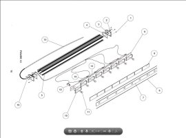
That wire is odd, you don't see large grounds going nowhere a lot. Maybe someone rewired it. Here isa factory exploded view.

arrow1.JPG
 

Forum Statistics

Threads
54,085
Messages
450,244
Members
19,152
Latest member
332

About Us

  • Since 1997, eLightbars has been the premier venue for all things emergency warning equipment. Discussions, classified listings, pictures, videos, chat, & more! Our staff members strive to keep the forums organized and clutter-free. All of our offerings are free-of-charge with all costs offset by banner advertising. Premium offerings are available to improve your experience.

User Menu

Secure Browsing & Transactions

eLightbars.org uses SSL to secure all traffic between our server and your browsing device. All browsing and transactions within are secured by an SSL Certificate with high-strength encryption.