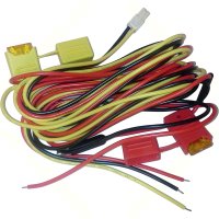
Motorola NNTN8527 power cable diagram needed asap

RecElect

Member
Jan 26, 2011
331
Loveland, Colorado
I have a customer supplied NNTN8527 apx vehicle charger "convertacom" and they did not supply the power cable to it. I have the stuff to make one, but I need a pinout. Anyone got one you could look at to send me the pinout on? Even a picture of the white power connector from the back side would be all I need. should have a red, yellow, and black wire in it. Thanks in advance!
 

Nolines

Member
Apr 5, 2018
1,681
Margate, FL
from motorolas pdf...

Red to Battery, Black to Ground, Yellow to Fuse panel either power all the time or Switched according to the diagram both red and yellow on a 5 amp fuse after power connection points..

The yellow wire controls whether or not the APX VA radio battery charger will be “live” at all times.
Consider the functionality and vehicle battery drain current below during installation.
Standard Wiring to Vehicle Switched A+ – Charging OFF with Vehicle OFF
For installations where the radio may be left in the APX VA with the vehicle’s ignition switched
OFF and minimal vehicle battery drain current is important, the standard wiring connection
of the yellow wire to vehicle switched A+ will disable charging.
Optional Wiring to Vehicle A+ – Charging ON with Vehicle OFF
When the radio is left in the APX VA for charging with the vehicle’s ignition switched OFF, the
optional wiring connection of the yellow wire to always-live vehicle (A+) will keep the charger ON.
When the operator takes the radio from the APX VA, low vehicle battery drain current will occur.

PDF is too large to post so heres the link to the pdf

https://www.motorolasolutions.com/c...s/chargers/APX_VehicularAdapter_UserGuide.pdf

Page 22 and 23 deal with power wiring
 

RecElect

Member
Jan 26, 2011
331
Loveland, Colorado
I appreciate the help, But I wasn't asking what colors went to what, or how it was hooked up. I physically didn't have the power connector with those wires in it so I had to make it and needed the pinout of that connector. Unless I am missing it, this pdf does not show the pinout of that connector specifically. I was able to get this information elsewhere though so it is all put together. Thanks though!
 

Nolines

Member
Apr 5, 2018
1,681
Margate, FL
sorry I found a Picture of it but couldnt find an actual pin out of what goes where, based on the picture i saw black to the left and yellow top right and red bottom right... I hope thats right... if it is please post it so anyone else who might bump into this similar issue will know what it is...3005297y03.jpg
 

Forum Statistics

Threads
54,111
Messages
450,324
Members
19,161
Latest member
ErikH

About Us

  • Since 1997, eLightbars has been the premier venue for all things emergency warning equipment. Discussions, classified listings, pictures, videos, chat, & more! Our staff members strive to keep the forums organized and clutter-free. All of our offerings are free-of-charge with all costs offset by banner advertising. Premium offerings are available to improve your experience.

User Menu

Secure Browsing & Transactions

eLightbars.org uses SSL to secure all traffic between our server and your browsing device. All browsing and transactions within are secured by an SSL Certificate with high-strength encryption.