MPC01 SC Transfer Issue

smallish

Member
May 8, 2020
84
Fremont, CA
Hello everyone,
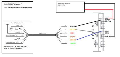
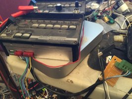
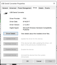
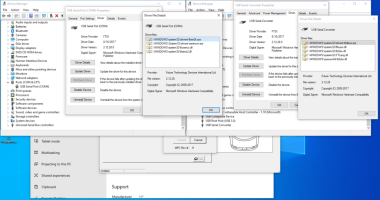
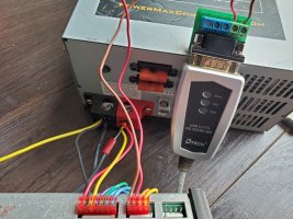
I'm currently trying to transfer an SC configuration to my MPC01, and when I click the 'Transfer to Transporter' button, it says 'Communications Failure.' I've checked the wiring and everything, and when I click the other transfer button, 'Transfer to MPC03', it still doesn't work. Also, when I open the programmer itself, a message pops up saying 'CommPort 1 is being used. Communications will be disabled.' Does anyone know what the problem here is? I will try to send pictures of my (temporary) setup if anyone needs them. Thanks!

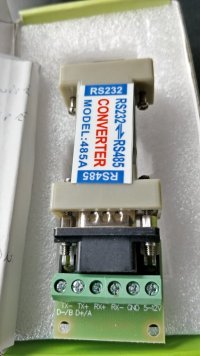
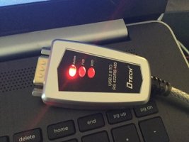
USB to RS485 converter that I used
 
Last edited:

smallish

Member
May 8, 2020
84
Fremont, CA
And you tried changing the comport correct?

I don't have a serial COM port on my laptop. Here is more information on my setup:

I connect the USB-RS485 serial data converter to the laptop USB port, and connect the TR+/TR-/GND to blue/gray/black wires accordingly (leaving the RX ports unconnected). 12v supply to the MPC01 red and yellow wires. I did the AIR HORN+button#9 before attempting to transfer. The error message was "communication failure".
I noticed before plugging in the USB port, I was only given the option to initialize 3 ports. After the plug-in, there is a "6" from the pulldown menu. Anyway, I tried both and nothing worked. Any feedback will be highly appreciated.
 

Nolines

Member
Apr 5, 2018
1,680
Margate, FL
You connect thru the bl627 I believe, at least that's how I did mine. The only other thing I would do is rerun thru the parameters for the communication to verify they match. Tried different usb port as well?
 

smallish

Member
May 8, 2020
84
Fremont, CA
I just realized that you were talking about the 5-wire comm port instead of the 9-pin COM port in the back of PC.

I thought the BL627 is not required for programming the MPC01. Is that not true? Out of the 5 comm pins on the MPC01, I only connected the blue and gray wires to the TR+ and TR- respectively.
 
Last edited:
when you open the software you need to click the "utilities" dropdown and "initialize com port" and choose the com port. the USB adaptor will make an available com port, then you need to have the controller plugged in and in programming mode then hit transfer, dont have the bar or anything else connected to the controller
 

smallish

Member
May 8, 2020
84
Fremont, CA
Thanks for the response. I did initialize the comm port before initiating the transfer but I will try plugging in the controller AFTER the port has been initialized.

I would like to make a correction on my first post. I don't see this message anymore "when I open the programmer itself, a message pops up saying 'CommPort 1 is being used. Communications will be disabled.' I am only getting the "communication failure" message during transfer.

As mentioned earlier, I am only using the laptop, USB-RS485 serial data converter and the MPC01 controller (no BL627 nor Lightbar is involved)
 

Nolines

Member
Apr 5, 2018
1,680
Margate, FL
Actually you connect the tx +- wires to the 485 to the mpc01 and leave them there and switch on the unit putting it in program mode before initiating the com port and transferring the files( but I'd read the mpc first to make sure the connection is good, do the changes then transfer back. Sorry I used to connect to the wires from my bl627 is what I meant when I said going through it. I dropped the manual for the 03 on the other thread but can drop the 01 file here if needed.
 

smallish

Member
May 8, 2020
84
Fremont, CA
Did you put the controller into programming mode?
Yes, I did the Air horn+button 9 and saw the sweeping lights.

Actually you connect the tx +- wires to the 485 to the mpc01 and leave them there and switch on the unit putting it in program mode before initiating the com port and transferring the files( but I'd read the mpc first to make sure the connection is good, do the changes then transfer back. Sorry I used to connect to the wires from my bl627 is what I meant when I said going through it. I dropped the manual for the 03 on the other thread but can drop the 01 file here if needed.

I have tried both. Initialize before and after enabling the program mode but still getting the same communications failure message.
Interesting that you mentioned reading from the mpc01 to prove that a good connection has been established. How do I do that? At this point, any piece of information would be helpful. Please share what you think may be helpful.

Thank you guys!
 

smallish

Member
May 8, 2020
84
Fremont, CA
I am wondering whether the USB-RS485 converter (without going through RS232) is the culprit. Do you guys program through the USB port of your PC or the Serial COM port (DB9)?
 

RS485

Supporting Donor
Aug 5, 2019
370
Central MA
I am wondering whether the USB-RS485 converter (without going through RS232) is the culprit. Do you guys program through the USB port of your PC or the Serial COM port (DB9)?
Yes, through USB-RS485 - attached is the setup I use and even tried Windows 10 laptop this morning for the first time. I use https://www.digikey.com/product-det...-ltd/USB-RS485-WE-1800-BT/768-1041-ND/2179735 as the USB/RS485 converter and have never had a problem.

While I haven't had any problems, I did stumble on this https://store.chipkin.com/articles/rs485-rs485-cables-why-you-need-3-wires-for-2-two-wire-rs485 and tied all my grounds together.

I just ordered the Dtech you pointed to. It should be here tomorrow :) I'll let you know how it goes.
 

Attachments

  • USBRS485MPCxx.png
    USBRS485MPCxx.png
    123.4 KB · Views: 16
  • MPC01.JPG
    MPC01.JPG
    154.4 KB · Views: 15
Last edited:

smallish

Member
May 8, 2020
84
Fremont, CA
Yes, through USB-RS485 - attached is the setup I use and even tried Windows 10 laptop this morning for the first time. I use https://www.digikey.com/product-det...-ltd/USB-RS485-WE-1800-BT/768-1041-ND/2179735 as the USB/RS485 converter and have never had a problem.

While I haven't had any problems, I did stumble on this https://store.chipkin.com/articles/rs485-rs485-cables-why-you-need-3-wires-for-2-two-wire-rs485 and tied all my grounds together.

I just ordered the Dtech you pointed to. It should be here tomorrow :) I'll let you know how it goes.

Thanks for sharing your wiring diagram and picture. I will try to take a picture of my setup later today and post it here. I have the converter's GND port and the MPC01's black wire connected to the negative terminal of PS. I noticed on your diagram you are connecting the "audio-" on the MPC01 to the negative as well. Is that a mistake in the drawing? It should be connected to the "Shield" pin instead? I don't have this connection but I will try later. What is the board that your blue and gray wires are attached to? Is it part of the digikey cable?
Do you think this is similar to the digikey? If so, I would to give it a try
 
Last edited:

RS485

Supporting Donor
Aug 5, 2019
370
Central MA
Hi: Yeah, I'm not sure the "audio-"->GND is necessary or correct. In any case, I just tried disconnecting every ground except the "J8" connected to the PS and I can't seem to force any comm errors.
The board in the pic is just a PCB with the connector on it so I can plug other devices in (i.e. BL10000, ULTRA, ISP, etc) - it has no circuitry.
Yeah! I believe that "WE 1800" is exactly what I have.
 

smallish

Member
May 8, 2020
84
Fremont, CA
This is what I use

Thanks. This is a RS232 to RS485 converter. Could you please how do you connect both ends? I assume the input end goes to the COM port of a PC? And the other end will have the TX+/TX-/GND/5-12v ports connected to the blue/gray/black/red?
 

Nolines

Member
Apr 5, 2018
1,680
Margate, FL
The rx +- is not used nor the gnd or the 5-12 v connection. Hold air horn and hilo and turn on the power when the lights are blinking she's in program mode! The blue grey wires are connected to the mpc01... Now I gotta get my connector from the car and look at my wire setup again... Ugh short term memory !
Ok tx blue +
Tx grey -
 

smallish

Member
May 8, 2020
84
Fremont, CA
Hi: Yeah, I'm not sure the "audio-"->GND is necessary or correct. In any case, I just tried disconnecting every ground except the "J8" connected to the PS and I can't seem to force any comm errors.
The board in the pic is just a PCB with the connector on it so I can plug other devices in (i.e. BL10000, ULTRA, ISP, etc) - it has no circuitry.
Yeah! I believe that "WE 1800" is exactly what I have.

Thanks for the confirmation. Please let me know how it goes with the Dtech converter.
 

smallish

Member
May 8, 2020
84
Fremont, CA
The rx +- is not used nor the gnd or the 5-12 v connection. Hold air horn and hilo and turn on the power when the lights are blinking she's in program mode! The blue grey wires are connected to the mpc01... Now I gotta get my connector from the car and look at my wire setup again... Ugh short term memory !

Thanks. So no need to connect the device to VDD nor GND. How is the other end connected to the PC?

By the way, how do you read from the mpc01?
 

RS485

Supporting Donor
Aug 5, 2019
370
Central MA
Hi "hi...":
I'm sorry to report that I received the Dtech part and it worked absolutely perfectly right out-of-the-box.
It worked on both Windows 7 and Windows 10 against both a MPC01 and MPC02.
The only slight wrinkle was that on Win7, it took a few moments to find and install the drivers...I just waited until it completed and then tested.
Note: I only connected the "T/R+" and "T/R-" terminals, nothing else (except PS +/- to "J8" on the MPCxx).
I wish I could report more useful news but I can't :(
 

Attachments

  • dtech.jpg
    dtech.jpg
    56.2 KB · Views: 9

smallish

Member
May 8, 2020
84
Fremont, CA
Hi "hi...":
I'm sorry to report that I received the Dtech part and it worked absolutely perfectly right out-of-the-box.
It worked on both Windows 7 and Windows 10 against both a MPC01 and MPC02.
The only slight wrinkle was that on Win7, it took a few moments to find and install the drivers...I just waited until it completed and then tested.
Note: I only connected the "T/R+" and "T/R-" terminals, nothing else (except PS +/- to "J8" on the MPCxx).
I wish I could report more useful news but I can't :(

Actually, that is a good news. I just have to follow the exact same setup. My dtech packaging looks a bit different than yours. Anyway, can you please verify the driver info for me?

Driver Provider: FTDI
Driver Date: 8/16/2017
Driver version: 2.12.28.0

The SC programmer version is 5.3.3

I will take some pictures of my hardware setup and post it later today. Thanks for all your help!
 

Attachments

  • Driver version.png
    Driver version.png
    44.2 KB · Views: 2

Nolines

Member
Apr 5, 2018
1,680
Margate, FL
are you sure the wires are hooked to the adaptor properly, they need to be in the proper places
Speaking of wires, do you have the power, ground, backlighting, etc etc etc connector with the wires going to the large molex connector that extends to all the other points that it needs to connect to??
 

RS485

Supporting Donor
Aug 5, 2019
370
Central MA
Actually, that is a good news. I just have to follow the exact same setup. My dtech packaging looks a bit different than yours. Anyway, can you please verify the driver info for me?

Driver Provider: FTDI
Driver Date: 8/16/2017
Driver version: 2.12.28.0

The SC programmer version is 5.3.3

I will take some pictures of my hardware setup and post it later today. Thanks for all your help!

Here's my Win10 driver details: (Note there should be a driver for both the "Port" and "Converter")
 

Attachments

  • win10.png
    win10.png
    270.5 KB · Views: 4

smallish

Member
May 8, 2020
84
Fremont, CA
Speaking of wires, do you have the power, ground, backlighting, etc etc etc connector with the wires going to the large molex connector that extends to all the other points that it needs to connect to??

Here is a picture of my wiring. Note: I do not have the right color coded wires for the J7. As you can see, the brown wire is the blue and red is the gray.

EDIT: The red (power) and yellow (backlit) wires are connected to the POS terminal of the power supply. The black (ground) wire goes to the NEG terminal. As for the DTECH device, the "blue" wire goes to the TR+ and "gray" wire goes to the TR-. I also tried with the GND connected to the NEG of PSU.

With everything plugged in, I turn on the PSU, MPC01 unit off (obviously backlit on) dial at RAD position, USB port connected to my laptop. Open the SC programmer, load my database, initialize PORT3, transfer to MPC01/transfer to transponder -> communications failure message
 

Attachments

  • 20200823_121042.jpg
    20200823_121042.jpg
    170.6 KB · Views: 9
Last edited:

RS485

Supporting Donor
Aug 5, 2019
370
Central MA
You don't have any LEDs lit on your Dtech...I always have the "Active" LED lit as soon as I plug it into the PC (even if not connected to the MPCxx). Did you just take this pic when the Dtech was disconnected from the PC?
 

smallish

Member
May 8, 2020
84
Fremont, CA
You don't have any LEDs lit on your Dtech...I always have the "Active" LED lit as soon as I plug it into the PC (even if not connected to the MPCxx). Did you just take this pic when the Dtech was disconnected from the PC?

Sorry for the confusion. The picture was taken when the USB was unplugged. I do get a red light on active when it is plugged in.
 

RS485

Supporting Donor
Aug 5, 2019
370
Central MA
So if you completely disconnect the Dtech from the MPC, then try to transfer...do you see about three quick green LED bursts on your Dtech's "TXD" LED? (I couldn't snap a photos of them 'cause they're so quick...but with my Dtech disconnectected from the MPC, they're clear as day when I try to transfer).
Next -- if I _don't_ have my MPC in "program" mode (i.e. no sweeping LEDs on the MPC) but connected with the Dtech, when I try to initiate a transfer, I see three green bursts on the Dtech's "TXD" LED followed by several green bursts on the Dtech's "RXD" indicating the MPC is sending (and the Dtech is receiveing) some kind of stuff. What do you see?
 

Attachments

  • dtechled.jpg
    dtechled.jpg
    35.8 KB · Views: 0

Nolines

Member
Apr 5, 2018
1,680
Margate, FL
Here is a picture of my wiring. Note: I do not have the right color coded wires for the J7. As you can see, the brown wire is the blue and red is the gray.

EDIT: The red (power) and yellow (backlit) wires are connected to the POS terminal of the power supply. The black (ground) wire goes to the NEG terminal. As for the DTECH device, the "blue" wire goes to the TR+ and "gray" wire goes to the TR-. I also tried with the GND connected to the NEG of PSU.

With everything plugged in, I turn on the PSU, MPC01 unit off (obviously backlit on) dial at RAD position, USB port connected to my laptop. Open the SC programmer, load my database, initialize PORT3, transfer to MPC01/transfer to transponder -> communications failure message
Twisted pair no straight wires allowed according to whelen and the mpc01 hilo and author switches held down when turning on mpc01 putting it in program mode with the 1 led on the mpc flashing then transferring the file.... Possible cause
 
Twisted pair no straight wires allowed according to whelen and the mpc01 hilo and author switches held down when turning on mpc01 putting it in program mode with the 1 led on the mpc flashing then transferring the file.... Possible cause
ive pulled out installs where they ran the data with speaker wires, the twisted isnt an issue
 

Forum Statistics

Threads
54,085
Messages
450,245
Members
19,152
Latest member
332

About Us

  • Since 1997, eLightbars has been the premier venue for all things emergency warning equipment. Discussions, classified listings, pictures, videos, chat, & more! Our staff members strive to keep the forums organized and clutter-free. All of our offerings are free-of-charge with all costs offset by banner advertising. Premium offerings are available to improve your experience.

User Menu

Secure Browsing & Transactions

eLightbars.org uses SSL to secure all traffic between our server and your browsing device. All browsing and transactions within are secured by an SSL Certificate with high-strength encryption.