Whelen CSP690 Xenon Bulbs to use?

kustern

Member
Jan 10, 2020
22
USA Idaho
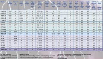
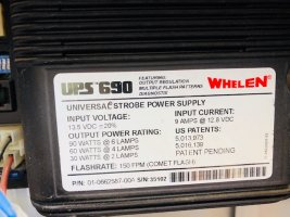
I understand that the Whelen CSP690 has 6 outputs with 15W each for a total of 90W.
What would happen if one would use a 50W bulb instead of a 15W?
Will I burn up the CSP690 or will the 50W bulb just produce 15W?
What if I just replace one of the 4 bulbs used with a 50W and the other three are left 15W?
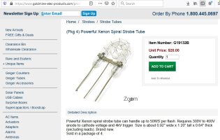
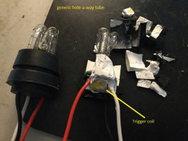
I found a source for inexpensive 50W Xenon lights...
 

Nolines

Member
Apr 5, 2018
1,680
Margate, FL
Isn't that 15 watts per outlet when all are in use? And higher when less outlets are in use? I may be off but I don't think that it would mess them up, are they turbo tubes or the old u shaped tubes which aren't as bright???
Who's your lucky source?( I know I'm asking slot there)
 

RS485

Supporting Donor
Aug 5, 2019
370
Central MA
I think the worst that could happen is that your 50-watt lamp wouldn't even flash. I don't think you could cause harm to the CSP690 because it has circuitry in place that will stop charging the capacitors when they've reached their maximum anode voltage at the conclusion of a charge cycle (with no working lamps connected).
The reason the 50-watt lamp might not fire is that it may require a higher anode voltage than the CSP690 is designed to deliver.
 
Last edited:

kustern

Member
Jan 10, 2020
22
USA Idaho
Xenon bulb
Requires 300V to 400V anode to cathode voltage and 4kV trigger.
Can handle up to 50W per flash.
 

Attachments

  • Xenon Spiral Strobe Tube.jpg
    Xenon Spiral Strobe Tube.jpg
    149.7 KB · Views: 15
  • Like
Reactions: Nolines

RS485

Supporting Donor
Aug 5, 2019
370
Central MA
I just hooked up a CSP690 and measured 557 volts with no tubes connected - certainly sufficient to fire your tube :)
 

kustern

Member
Jan 10, 2020
22
USA Idaho
Thanks for the reply, I'm gonna get me some of these to put on the shelf. I think last I checked I had one out of my four burnt out so I'll try this.
 

RS485

Supporting Donor
Aug 5, 2019
370
Central MA
Cool but what you're getting is just a raw tube. You'll have to put a trigger coil in there somewhere. Are you hip to that?
For instance, here's some old Whelen aircraft heads I re-tubed. There's a trigger coil in there that needs to deliver that "4kV" pulse to cause the ionization in the tube.
 

Attachments

  • retubes.jpg
    retubes.jpg
    123.9 KB · Views: 8
Last edited:

shues

Lifetime VIP Donor
May 21, 2010
10,293
NW Indiana
I seem to recall some of Whelen's old DOT series strobe power supplies being capable of delivering more than the common maximum of 22.5 watts per head of most modern regulated supplies.
 

firebuff17

Member
Mar 28, 2011
776
CT
Going on memory here and have only used one power supply myself but...
CSP690 are regulated and are 15w per head.
UPS690 was unregulated and would deliver 22.5w per head.

I used a UPS690 back in the day when I used strobes.
 

kustern

Member
Jan 10, 2020
22
USA Idaho
RS485 you stated "You'll have to put a trigger coil in there somewhere".
I have no idea how my system is wired OR how it works but there is this "black box" wired into the mix.
Does every bulb have to have it's own trigger and does it need to fire independently for each bulb and each flash OR???
Can the CSP690 handle any of the trigger signaling if needed?
I need someone to teach me how this all works...
I did see that some of the bulbs apparently have built in trigger coils but I think on my vehicle the bulbs look just like the one i sourced with just 3 leads.
 

Attachments

  • Box.jpg
    Box.jpg
    41.2 KB · Views: 7

kustern

Member
Jan 10, 2020
22
USA Idaho
RS485 - I do recall something similar to the "RETUBES" bulb picture that you posted where the bulb had quite a lot of silicone around the bottom where it was fitted to the light fixture. If there also is a trigger coil inside the silicone I do not know.
 

kustern

Member
Jan 10, 2020
22
USA Idaho
firebuff17 -
There is also a UPS690 wired into the mix!!!
Again I don't know what is actually powering the bulbs on my vehicle. I thought that the UPS690 was only a power supply and not a "Blinker"?
Can the UPS690 and the CSP690 be used individually?
Per the pic it looks like the UPS690 is also 15W per bulb.
 

Attachments

  • UPS690.jpg
    UPS690.jpg
    102.2 KB · Views: 5

RS485

Supporting Donor
Aug 5, 2019
370
Central MA
Given both a UPS690 or CSP690, whatever you plug into them, they will need a trigger coil to flash.
The trigger coil takes the trigger pulse from the power supply (on the white wire usually) which is ~200+ volts and transforms it to ~4K or more to ionize the Xenon gas within the tube.
I'm _not_ an authority on this stuff. I just find it absolutely fascinating that the raw physics of Xenon (and other tube mixtures) work this way and I totally enjoy digging into and exploring this kind of stuff (which isn't terribly useful or practical now the LEDs have been shown to be a superior source of light).
But with respect to your original post, NO you won't hurt the power supply but NO: without a trigger coil in the loop, I don't see how your tubes would flash (as a matter or physics).
I get the feeling that you have a pile of stuff that really needs to be de-tangled (disentangled) to make clear sense of what you have and what you might expect from your experiment.
 

Attachments

  • triggercoil.png
    triggercoil.png
    744.2 KB · Views: 13

MtnMan

Member
Dec 20, 2012
1,533
Eastern PA
Xenon bulb
Requires 300V to 400V anode to cathode voltage and 4kV trigger.
Can handle up to 50W per flash.
The tube shown in the pic has a trigger (the wire wrapped around the outside and connected to the center pin). You’ll need to identify the outer pins as the anode and cathode.
 

kustern

Member
Jan 10, 2020
22
USA Idaho
So it appears that every bulb has to have its own trigger pulse? Or would imagine if two bulbs are fired at the same time then possibly they could use the same trigger signal ?
It appears that all 6 outputs on the CSP690 have 3 wires, Anode - Cathode and Trigger. And then I would assume that the trigger is a separate signal for each output.
I think in my case I just have to replace the one burnt out bulb, the tree wires should be easy to decipher and then just dig a bit and see if the bulb that I replace has a coil built in, if not then it is located somewere else and should work as is.
I also read that the bulbs will deteriorate with usage and over time, so hopefully it will work just replacing one. Also read that the system should be used at least once every year. If dormant for longer time it may damage the system when powered up!
Sounds like LED would be much easier!!!
 
Last edited:

RS485

Supporting Donor
Aug 5, 2019
370
Central MA
I think your black box may be a Whelen headlight flasher. This device doesn't play any role in your CSP690 strobe system but I'm wondering if all you really need is a replacement hide-a-way/hide-a-flash strobe tube. Search "whelen HAW" in eBay. You'll see what I mean (trigger coil built in).
 

RS485

Supporting Donor
Aug 5, 2019
370
Central MA
FYI - Here's an off-brand tube dissected to show the trigger coil.
 

Attachments

  • cut-a-way.jpg
    cut-a-way.jpg
    178.6 KB · Views: 14

kustern

Member
Jan 10, 2020
22
USA Idaho
Thanks for all the info. I'll look into this when weather settles down, been snowing like crazy out west lately!
Yes I think only a small part of the Whelen system is still set up functional. I believe there are only 4 Strobe bulbs installed and working right now on a Safari Van (I think 3 operational). Two in the front parking lights and two in the tail lights.
How does the Head-Light-Flasher work, and will that operate the actual main head light bulbs OR would it be a separate bulb? What kind of components would be controlling this setup if the CSP690 is not involved?
 

RS485

Supporting Donor
Aug 5, 2019
370
Central MA
The headlight flasher's control depends on which actual model it is. After puzzling over your "black-box" pic, I googled and found
which looked pretty similar. However this is a BL2150A which is part of a 2-wire "B-LINK" network controlled via serial communications. If this were the case in your case, I'd expect your power supplies to be from the same family (i.e. "ISP" or "BL" family, not CSP690 or UPS690). So I'm guessing your headlight flasher is just a conventional device (not controlled by serial communications) so I'm guessing its this device:
https://www.whelen.com/install/135/13510.pdf
but I can't find a pic to confirm.
I think the best thing you can do (when the weather settles down :) ) is take a thorough inventory and layout of exactly what you have. I may take some time but it will be well worth it to get the most out of whatever you have.
 

RS485

Supporting Donor
Aug 5, 2019
370
Central MA
I use these:
but my re-tubes are just for restoration of old stuff - I can't tell you how they'd perform in a professional situation.
Pins 1&3 connect to ground
Pin 2 connects to the power-supply's trigger wire (usu white).
The white wire coming out of the top of the trigger coil connects to the tube's trigger wire (the thin wire usually wrapped around the outside of the tube as MtnMan described.
 

kustern

Member
Jan 10, 2020
22
USA Idaho
RS485
thanks for all the info. You were right, the "black box" is a head light flasher. Got it all working!! Fun stuff. Wish I had some time to play with the Xenon bulbs and trigger coil/transformer. Gonna put some on the shelf so when a rainy day comes by and I don't have anything else to do I can make some flash experiments! I have seen the bulbs I indicated go on sale for $8, that's 2$ per bulb. Cant beat that...I think!! I really don't know since I am all new to this.
 
  • Like
Reactions: RS485

RS485

Supporting Donor
Aug 5, 2019
370
Central MA
Also according to the attached, the CSP690 does not have output regulation while the UPS690 does.
 

Attachments

  • 10378.pdf
    852 KB · Views: 1

Nolines

Member
Apr 5, 2018
1,680
Margate, FL
You do understand that the power supply is the trigger source for the bulbs, that's what all the connections are for, red black and white ( the trigger wire ) correctly insulated and connected to an amp or Deutsch connector and run to the power supply and power applied to the correct outlets and the strobes fire off in whatever pattern you chose!
 
  • Like
Reactions: RS485

kustern

Member
Jan 10, 2020
22
USA Idaho
Yes I am slowly understanding how it works. The power supply has 3 wires, that provide two different voltages. The Anode-Cathode 300-400V and the Trigger that is about 200-300V. The trigger will need to be transformed to a higher voltage of about 4kV to be able to light the gas.
So, to start off the two voltages are separated. I would assume that the trigger voltage is a pulse. Is the Anode-Cathode voltage also a pulse since it appears that it is derived from a capacitor?
Is the Anode-Cathode voltage applied first and then the Trigger?
 
  • Like
Reactions: RS485

RS485

Supporting Donor
Aug 5, 2019
370
Central MA
One of the greatest sources of information for this stuff are the patents from the engineers who created it in the first place.
google US3515973, US4013921, US4321507, US5013973 and definitely keep an eye out for ANY Xenon discharge patent from Scott Sikora (Tomar) too.
Also google "Don Klipstein Strobe". There's some seriously good material here too.
 

kustern

Member
Jan 10, 2020
22
USA Idaho
Thanks, I will read through that stuff. I would think that the neon-signs are fired similarly? Most likely the Anode-Cathode voltage is held on constantly and when the trigger is activated the tube light up and stay lit? OR maybe I am completely wrong here and they do have to be 'pulsed' too?
 

RS485

Supporting Donor
Aug 5, 2019
370
Central MA
:) you might want to start with the '507 patent. The designer leveraged a neon lamp to sense when desired anode voltage was achieved.
The power supply is working feverishly between flashes to "accumulate" the target anode voltage which, by the way, is why you need to be REALLY CAREFUL to avoid the dangerous voltage present in these power supplies.
The primary capacitors (thus the anode voltage) is at the lowest level just after they "dumped" to make the flash happen. The more modern the power supply's design, the faster they become dangerous again. This led to the problem of tube de-ionization. If the inverter keeps doing its job, the tube will stay on (much like a neon lamp - not too bright, just a glow) and you won't store anything up in the caps.
 

kustern

Member
Jan 10, 2020
22
USA Idaho
You said "If the inverter keeps doing its job, the tube will stay on" ? Have to figure out what the 'inverter' is, then things may clear up a bit.
 

Forum Statistics

Threads
54,090
Messages
450,253
Members
19,152
Latest member
332

About Us

  • Since 1997, eLightbars has been the premier venue for all things emergency warning equipment. Discussions, classified listings, pictures, videos, chat, & more! Our staff members strive to keep the forums organized and clutter-free. All of our offerings are free-of-charge with all costs offset by banner advertising. Premium offerings are available to improve your experience.

User Menu

Secure Browsing & Transactions

eLightbars.org uses SSL to secure all traffic between our server and your browsing device. All browsing and transactions within are secured by an SSL Certificate with high-strength encryption.