JohnMarcson
Administrator
Too late....I *almost* bought that, but decided it didn't really fit in my collection. Glad you've got a new toy, just hope it doesn't further distract you from unloading your car...
Too late....
I got the transformer reconnected and now it just winds up and doesn't fire. Anything for troubleshooting that I should do differently on this type? I honestly haven't even unpacked it enough to look for obvious culprints. I'm wondering if the bulb just isn't bad.That's a really nifty device.
I found some interesting hits:
this link discusses the choice of using a "Signalite" spark-gap for timing/triggering (reasons its prefered over a neon lamp)
and this link from ~71 discussing uses on school buses.
Interesting is that the two Rae Co individuals named in the links share a last name of "Elvers".
When researching the Whelen SYNC box, I came across some PSs that used that spark-gap device for timing/triggering.
 and of course, assuming it charges up with enough voltage to jump the gap, should see a slight spark in the spark-gap.

Thanks. The "small current sensing transformer" was completely loose in the "can". I reconnected it and it made the wind up noise. Prior to that, it made no attempts to live at all. I will get this thing to my bench and start testing. I hope the bulb isn't bad, I don't recognize it, I'll take some pics. Thanks for the info, I will update this thread.Really need more info (in the form of clear pics, both sides of the PCB).
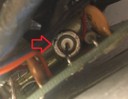
Assuming the link I pointed to above describes your device and assuming the spark-gap looks like this:
View attachment 241962 and of course, assuming it charges up with enough voltage to jump the gap, should see a slight spark in the spark-gap.
However, from what I can tell, "newer" spark-gaps were more sealed up and I don't know if you could see anything inside.
I see what looks like a small transformer and a relatively large coil.I'm confused as to what does what (why I love to see clearer pics of the layout).
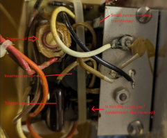
Update: Ah, okay - now I recognize a bit more:
View attachment 241963
Bulb's red-wire connects to the trigger coil, brown to ground, orange to primary cap(s) anode.
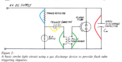
So tests using a diagram found in the link above:
View attachment 241965
- I'd expect somewhere near of avove 300V at RED
- Zero ohms resistance across both GREEN points
- guessing around 230V across YELLOW (fluctuating if its working -- i.e. as it charges and discharges)
- BLUE should measure to be close to the resistance value of this resistor under test.
The "G.D. DEVICE" is the spark gap BTW.
HTH
This is a really cool device worthy of working correctly...for sure
Pretty much, but no actual outer tube. The small transformer and the socket were both failure points as well as a questionable ground lead. They used soooooooo much silicone to hold this thing together it looked almost homemade, but the spot for the strobe is professionally cut out. The strobe bulb looks like the glass vacuum tube cover was removed, there is a lip on the bulb from where it would have been. The light is just odd; so much trouble for such a questionable product. I am going to reassemble it when the new socket I ordered arrives. Here is a video.
Thanks. The amount of white epoxy they used was close to amateur level and made me feel less bad about rebuilding it in a similar way. I like the idea of random components from different sources being combined into a "factory" package. The vacuum tube style tube and socket were new ones for me. The fact that they very specifically cut out the metal for the bulb but it still barley cleared was also interesting. I'm glad I added it to the collection and that it is working.This is a really really neat looking strobe...and very novel in design -- I'm glad you got it working. Kudos!

