Installation 23
5.5
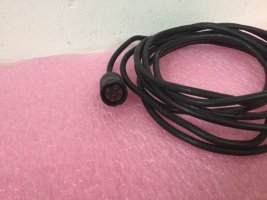
Emitter Cable Connector Pin Index
Table 5-1 lists the pin index for the Model 792H,
792L, 792T or 792HF emitter cable connector.
Figure 5-11 shows the pin view of the emitter
cable connector and Figure 5-12 shows the socket
view.
Table 5-1. Emitter Cable Connector Pin Index
Pin Wire Color Function
1 Red +12 VDC
2 Orange Range setting enable (input)
3 White Disable (input)
4 Gray 1708 COM (-)(B)
5 Green DC return for indicator light
6 Black DC negative/ground/chassis
7 Blue 1708 COM (+) (A)