Running two sirens indoors with resistors

JohnMarcson

Administrator
May 7, 2010
10,971
Northwest Ohio
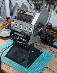
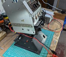
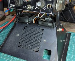
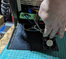
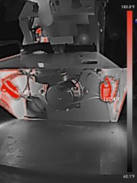
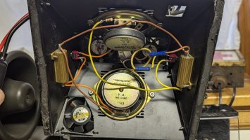
I have a "demo" setup to run two sirens "momentarially" at safe volume indoors. The setup uses a resister for each siren and has a red cutoff button on each side in case you want to mute one siren for a moment. I will upload a video later, but right now I have a 58w Federal from 1970 and a 100w Whelen from 1980 installed (the 5 switches between the sirens don't do anything at this time). Before any cooling the 100w side was heating up to 235°F internally (over 200°F external housing) and the 58w side was heating up to 195°F internally (over 170°F externally). At that point (around 6-10 min) there would be smells and sounds of component damage. I wanted to see if I could run them longer with some cooling, so I added two intake fans and one exhaust on the side of the 100w siren's resistor. After intake fans at the top and an exhaust fan on the 100W side I got things under control and able to run continuously, although I wouldn't risk a pricey or new siren on the setup. I am still messing around with some heat sinks and other resistors. For now, the 100w one is down to approx. 180°F internally and the 58w down to approx. 160°F internally with steady usage (the numbers top out at 10 min and didn't change after another 10). That translated to external housing temps that were significantly lower as well. Here is the setup and the results.

Setup
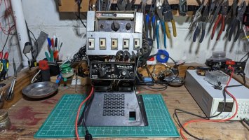
setup1.jpg
setup3.jpgsetup2.jpg

Intake Fans
front fans.jpg

Exhaust fan behind the 100w side.
rear fan.jpg

Airflow concept (note air exhausts around the speakers too).
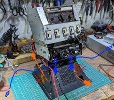
airflow.jpg

Some thermal images after running for 10 minutes. The 100w Whelen uses the resistor on the Left when facing the unit (the one with the exhaust fan behind it).

100w Whelen side (external), 160°F max hold temp
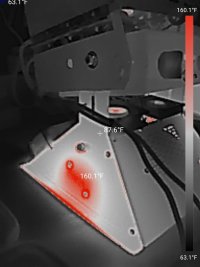
tempoutside 100.jpg

58w Federal side (external) 125°F hold temps
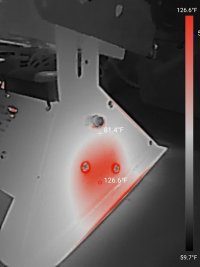
temp outside 58.jpg

100w Whelen side (internal) 190°F approx. hold temps
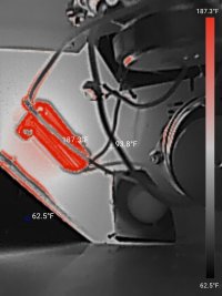
temp100w.jpg

58w Federal side (internal) 160°F Approx. hold temps
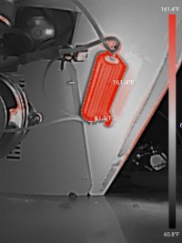
temp58  watt.jpg

Both with the base lifted more
temps under.jpg
 

JohnMarcson

Administrator
May 7, 2010
10,971
Northwest Ohio
My wife got me a new one when I moved the lab indoors. I am not sure if that was nice or a subtle dig.

I also tried the fans in reverse, thinking heat rises, but it was actually less effective.I assume there was less airflow directly over the resistors. I will keep playing until it breaks, catches fire, or it becomes a temp I am more comfortable with.
 

Dave F

Moderator
Sep 13, 2015
1,343
Berks County, PA
Ok. To each their own by all means

I’m a light guy, I’ve never been into the vintage lights, let alone sirens. So maybe my question will help those newer to the community

Why would one need/want this setup? Demo the sounds? Are they operating at the full 100w? Please forgive my naivete
 

JohnMarcson

Administrator
May 7, 2010
10,971
Northwest Ohio
Ok. To each their own by all means

I’m a light guy, I’ve never been into the vintage lights, let alone sirens. So maybe my question will help those newer to the community

Why would one need/want this setup? Demo the sounds? Are they operating at the full 100w? Please forgive my naivete
It lowers the volume to safe db levels while keeping the tones pretty true to form by using resistors.


There is some debate as to whether it damages some newer sirens, for those I have a speaker muffled with foam. It brings the volume down but there is distortion in the tones.


  • Like
Reactions: stansdds and Dave F

RS485

Supporting Donor
Aug 5, 2019
370
Central MA
It lowers the volume to safe db levels while keeping the tones pretty true to form by using resistors.


There is some debate as to whether it damages some newer sirens, for those I have a speaker muffled with foam. It brings the volume down but there is distortion in the tones.


Could you share a schematic? What resistor values are you using?
I'd love to understand your design with MtnMan's post in mind (something about how to calculate voltage drop - very cool!).
Thanks!
 

JohnMarcson

Administrator
May 7, 2010
10,971
Northwest Ohio
Could you share a schematic? What resistor values are you using?
I'd love to understand your design with MtnMan's post in mind (something about how to calculate voltage drop - very cool!).
Thanks!

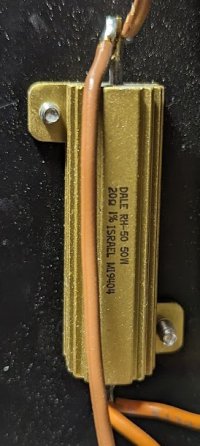
I will take some pictures. I actually got this unit from an Able 2 dealer pre-assembled, I just added fans. I also have some loose resistors that i have been experimenting with using some old car audio speakers and it has worked pretty similarly. Heat seems to be the enemy, but i also have questions as to why people report this damages Whelen sirens when Federal has directly recommended it in their literature.

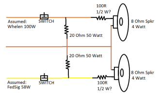
Brown is the speaker common wire from both sirens, yellow is positive from one siren, and orange positive from the other.

PXL_20230324_140433371.PORTRAIT.jpg
PXL_20230324_130422550.PORTRAIT.ORIGINAL.jpgPXL_20230324_140523629.PORTRAIT.jpgPXL_20230324_140516378.PORTRAIT.ORIGINAL.jpg
 
Last edited:

shues

Lifetime VIP Donor
May 21, 2010
10,300
NW Indiana
Instead of using a single resistor of a particular value, consider using four resistors of that value in a 2x2 series/parallel arrangement. The end result offers the same resistance, but the heat is distributed across four resistors. Naturally, four resistors have four times the surface area to dissipate the heat.
 

JohnMarcson

Administrator
May 7, 2010
10,971
Northwest Ohio
Instead of using a single resistor of a particular value, consider using four resistors of that value in a 2x2 series/parallel arrangement. The end result offers the same resistance, but the heat is distributed across four resistors. Naturally, four resistors have four times the surface area to dissipate the heat.
That's not a bad idea. I think I'm done messing with this, it runs for 10 minutes which is way longer than I am going to use it. I think I need to make my "muffled speaker" style one have less distortion; that one I feel comfortable using rare sirens on.
 

RS485

Supporting Donor
Aug 5, 2019
370
Central MA
FWIW, here's my take on it: (I did find some web hits indicating the speakers are rated at 4 watts).
1679684316327.png
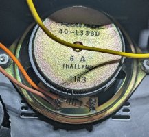
My naive interpretation is that the big resistors are meant to "pull" a load from the siren amplifier (though not near 100% load). The small resisters in series with the speaker look to me like brown/black/brown...i.e. 100 Ohm, and appear to be about the size of 1/2 watt...but if I really zoom in, the third band almost looks red...which would make it a 1K resistor. Either way, it seems like it's meant to just take a sip off the feed from the amplifier to pass on to the speaker.

The one concern I have is the placement of the switch (which I may have misinterpreted).
If the switch is pressed (to break contact), then the siren amp will see _no_ load. I *thought* this could cause EMF back-feed from the primary coil to the drive transistors, within the siren amp. I thought I read somewhere (maybe on ELB even) that "newer" siren amps had circuitry to bypass this to ground. It seems safer to put the switch on the other side of the power resistor(s) so the amp always sees substantially the same load.

Overall, this seems kind of like an LPAD pegged at a specific mid-point.
I agree with @shues recommendation of 4 resistors arranged as described...at least on the 100W side.

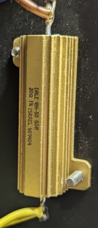
I don't trust my math yet but but without bothering too much with details (treating it as DC and ignoring the resistor-speaker as attached in parallel), 33V into 20 Ohms is 1.65 Amps/54 watts...just a bit greater than the 50watt resistor rating.

My $0.02
 

JohnMarcson

Administrator
May 7, 2010
10,971
Northwest Ohio
FWIW, here's my take on it: (I did find some web hits indicating the speakers are rated at 4 watts).
View attachment 243457
My naive interpretation is that the big resistors are meant to "pull" a load from the siren amplifier (though not near 100% load). The small resisters in series with the speaker look to me like brown/black/brown...i.e. 100 Ohm, and appear to be about the size of 1/2 watt...but if I really zoom in, the third band almost looks red...which would make it a 1K resistor. Either way, it seems like it's meant to just take a sip off the feed from the amplifier to pass on to the speaker.

The one concern I have is the placement of the switch (which I may have misinterpreted).
If the switch is pressed (to break contact), then the siren amp will see _no_ load. I *thought* this could cause EMF back-feed from the primary coil to the drive transistors, within the siren amp. I thought I read somewhere (maybe on ELB even) that "newer" siren amps had circuitry to bypass this to ground. It seems safer to put the switch on the other side of the power resistor(s) so the amp always sees substantially the same load.

Overall, this seems kind of like an LPAD pegged at a specific mid-point.
I agree with @shues recommendation of 4 resistors arranged as described...at least on the 100W side.

I don't trust my math yet but but without bothering too much with details (treating it as DC and ignoring the resistor-speaker as attached in parallel), 33V into 20 Ohms is 1.65 Amps/54 watts...just a bit greater than the 50watt resistor rating.

My $0.02
That seems like what it is doing. I honestly don't use the "cut off buttons" so I can't say for sure if they are problematic, but that does seem to be a wierd spot for them. The buttons just seem unnecessary since you can't run it for very long anyway. The resistor at the speaker is Brown, Green, Red, Gold, which I think is a resistance of 1.5K Ohms, rated at 0.5 W (close enough).

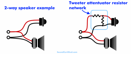
Kind of like you said, a l-pad setup with no dial.


pad.PNG

The resistors get way too hot so I assume more surface area is needed like shues said and/or a different rating of resistor. I use it for maybe a minute at a time with the current sirens so I'm not too worried about working on it. I would like to know the potential for siren damage and what the root cause is for that.
 
Last edited:

RS485

Supporting Donor
Aug 5, 2019
370
Central MA
so if, "The (20 ohm) resistors get way too hot", then what if they were 40 or 50 ohm? What reason is there _not_ to choose them?
 

shues

Lifetime VIP Donor
May 21, 2010
10,300
NW Indiana
As you already know, but as others reading this thread may not, selecting a 40 ohm or 50 ohm resistor would result in reduced output as compared to a 20 ohm resistor. The siren would be somewhat quieter when connected through a higher value resistor.
 

RS485

Supporting Donor
Aug 5, 2019
370
Central MA
As you already know, but as others reading this thread may not, selecting a 40 ohm or 50 ohm resistor would result in reduced output as compared to a 20 ohm resistor. The siren would be somewhat quieter when connected through a higher value resistor.
I don't see that...if this resistor is higher in value (and is in _parallel_ with the speaker+its resistor), it would "suck less" from what's put out by the amplifier.

I think the speaker+its 1500ohm resistor, would see _more_ power...thus be louder. If I'm wrong, please set me straight! (or tell me to STFU -- this siren stuff is _not_ my bag).
 

shues

Lifetime VIP Donor
May 21, 2010
10,300
NW Indiana
As compared to the 100-ohm, or 1000-ohm, series resistor, the speaker's actual resistance is probably negligible. For argument's sake:

The speaker and the 100 ohm resistor in series present, let's say, 105 ohms of resistance together as a combination:
  • The 105 ohm combination and the 20 ohm resistor in parallel present about 16.8 ohms of resistance to the siren, drawing just shy of 2 amps for a power output of about 66 watts.
  • The 105 ohm combination and a 50 ohm resistor in parallel present about 33.9 ohms of resistance to the siren, drawing just shy of 1 amp for a power output of about 33 watts.
The speaker and the 1,000 ohm resistor in series present, let's say, 1,005 ohms of resistance together as a combination:
  • The 1,005 ohm combination and the 20 ohm resistor in parallel present about 19.6 ohms of resistance to the siren, drawing just shy of 1.7 amps for a power output of about 55 watts.
  • The 1,005 ohm combination and a 50 ohm resistor in parallel present about 47.6 ohms of resistance to the siren, drawing just shy of 0.7 amps for a power output of about 23 watts.
Please check my math. I've rounded several times along the way, probably compounding any errors in my calculations.
 
Last edited:
  • Like
Reactions: RS485

RS485

Supporting Donor
Aug 5, 2019
370
Central MA
In each bulleted point, when you say, "resistor in series present", do you mean "resistor in parallel present"? -- According to this calculator your math makes perfect sense.

What I'm trying to grok is the differing voltage drop caused by variations of the power resistor (20 or 50) and what effect it has on the speaker(+plus its small resistor in series). I.e:


All other things being equal, the speaker in series with a 1500 ohm resister will be quieter than with a 100 ohm resistor but I'm trying to understand the effect in varying the power resistors in parallel with the speaker config.

In any case, thanks for your detailed math and digging into it! I really appreciate it!


UPDATE: By the very article I pointed to, I realize my confusion as to how peers perform in a parallel circuit: Each peer node "sees" the same voltage presented by the siren amp, and consumes its fraction of power according to its resistor. They are not influenced by each-other in a perfect world.

There is voltage drop in series circuits and that is how/why the small speaker is protected from seeing the raw 33 volts typical of a 100W siren amp.

The heat-burner...the 20 or 50 (or whatever) peer resistor in this parallel circuit is present _only_ for the purpose of presenting a load to the siren amp.

Is this done out of elecrical necessity or sound aesthetics? (i.e. does the load cause the siren amp to behave differently where under this load, it sounds better). @JohnMarcson -- if you happen to have chance to vary this load resistor, please let us know if you hear any diff in sound!
 
Last edited:

JohnMarcson

Administrator
May 7, 2010
10,971
Northwest Ohio
What series is the Federal PA15A? 1B, 1C, 1D, or 1E?
PA15A.... I will cut it free from my the resistor tester and sell it if someone else wants it. I'm not really a Federal siren collector.
 

Wailer

Member
May 24, 2010
2,294
Canada
PA15A.... I will cut it free from my the resistor tester and sell it if someone else wants it. I'm not really a Federal siren collector.
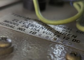
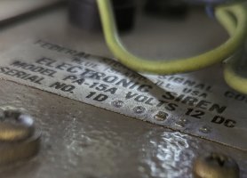
There is a silver label on the bottom of the PA15A. The first two digits of the serial number are black and indicate which series.
 

JohnMarcson

Administrator
May 7, 2010
10,971
Northwest Ohio
There is a silver label on the bottom of the PA15A. The first two digits of the serial number are black and indicate which series.
1D
PXL_20230329_134855762.PORTRAIT.jpg
 

JohnMarcson

Administrator
May 7, 2010
10,971
Northwest Ohio
There is a silver label on the bottom of the PA15A. The first two digits of the serial number are black and indicate which series.
1D - There is a date of 1969 stamped on it somewhere too
PXL_20230329_134855762.PORTRAIT.jpg
 

Wailer

Member
May 24, 2010
2,294
Canada
1D - There is a date of 1969 stamped on it somewhere too
View attachment 243571
Then you have one of the good ones. Series 1B, 1C, and 1D sing. Very musical sounding sirens. I have a 1B and a 1D.

Series 1E screams. I can't stand the sound of that version. It's high-pitched like the sirens we hear nowadays. I don't have one of those, but I have a PA20A series 2E which is the same thing except for the hi-lo tone.

I've heard the 1980s vintage Whelen WS295 sirens too. They have low pitched wail and yelp tones something like the PA15A series 1D, although they look and sound closer to the Carson / Southern VP SA400.
 
  • Like
Reactions: Maxim2Eng

JohnMarcson

Administrator
May 7, 2010
10,971
Northwest Ohio
Yep, that Whelen sounds just like the Southern VP SA400. Where I live the ambulance service was using SA400s in the early to mid 1980s.
The first two ambulances I drove had SVP sirens. I liked the wail, wasn't crazy about the tone 3.
 

JohnMarcson

Administrator
May 7, 2010
10,971
Northwest Ohio
As a volunteer fire fighter in college, the county pumper (Boyle Co. Engine 1) had a FS Director series 1D and a Q2B on a Ford cab over chassis…very nice apparatus (1,000 GPM, 750 gal booster tank). I would set the Director to Yelp and wind up the Q…Best sound combination ever!
A good electronic siren on yelp backing a Q brings back memories....
 

Wailer

Member
May 24, 2010
2,294
Canada
As a volunteer fire fighter in college, the county pumper (Boyle Co. Engine 1) had a FS Director series 1D and a Q2B on a Ford cab over chassis…very nice apparatus (1,000 GPM, 750 gal booster tank). I would set the Director to Yelp and wind up the Q…Best sound combination ever!
Yeah, the 1D would sound good with the Q. Both are within the same frequency range.
 

Forum Statistics

Threads
54,168
Messages
450,502
Members
19,179
Latest member
Ragnarok

About Us

  • Since 1997, eLightbars has been the premier venue for all things emergency warning equipment. Discussions, classified listings, pictures, videos, chat, & more! Our staff members strive to keep the forums organized and clutter-free. All of our offerings are free-of-charge with all costs offset by banner advertising. Premium offerings are available to improve your experience.

User Menu

Secure Browsing & Transactions

eLightbars.org uses SSL to secure all traffic between our server and your browsing device. All browsing and transactions within are secured by an SSL Certificate with high-strength encryption.