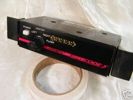
i have an older arrowstik as-10 with the following wire colors, black, yellow, orange, blue, grey, brown, & green. i know black is the positive & each other color matches a segment on the light when i power it. my problem is all the diagrams i have found for the controller, dont match the colors i have. unfortunately, the box doesnt have the schematic on it. i opened it up as well & the only reference i could find is that is p/n 7458. this is the code3 box with the selector knob & power switch. it doenst have the buttons for dimming etc. any suggestions, insight as to how i can connect the 2?
You are using an out of date browser. It may not display this or other websites correctly.
You should upgrade or use an alternative browser.
You should upgrade or use an alternative browser.
arrowstik wiring question
- Thread starter johnnotponch
- Start date
Your Code 3 ArrowStik controller should have a 7-pin green plug on the back of it, and also one black flying lead with a yellow male 1/4" quick disconnect at the end.
The controller probably looks something like this:

The green plug is normally wired like this:
[Broken External Image]:http://img837.imageshack.us/img837/5096/greenplug.png
An AS-10 is normally found to be wired something like this:
[Broken External Image]:http://img148.imageshack.us/img148/9027/as10.png
The following instructions ought to be of some value to you. You will need to substitute the correct wire colors for your ArrowSitk.
On the back of the controller:
The flying lead (black) should be connected to ground.
On the green plug:
The wire at position seven (depicted as red) should be connected to +12v DC.
The wire at position one (depicted as brown) should be connected to the farthest right segment of the ArrowStik.
The wire at position two (depicted as orange) should be connected to the right-center segment of the ArrowStik.
The wire at position three (depicted as violet) should be connected to the center segment of the ArrowStik.
The wire at position four (depicted as yellow) should be connected to the left-center segment of the ArrowStik.
The wire at position five (depicted as blue) should be connected to the farthest left segment of the ArrowStik.
On the ArrowStik harness:
The black lead, which you already know is for power, should be connected to +12v DC.
The controller probably looks something like this:

The green plug is normally wired like this:
[Broken External Image]:http://img837.imageshack.us/img837/5096/greenplug.png
An AS-10 is normally found to be wired something like this:
[Broken External Image]:http://img148.imageshack.us/img148/9027/as10.png
The following instructions ought to be of some value to you. You will need to substitute the correct wire colors for your ArrowSitk.
On the back of the controller:
The flying lead (black) should be connected to ground.
On the green plug:
The wire at position seven (depicted as red) should be connected to +12v DC.
The wire at position one (depicted as brown) should be connected to the farthest right segment of the ArrowStik.
The wire at position two (depicted as orange) should be connected to the right-center segment of the ArrowStik.
The wire at position three (depicted as violet) should be connected to the center segment of the ArrowStik.
The wire at position four (depicted as yellow) should be connected to the left-center segment of the ArrowStik.
The wire at position five (depicted as blue) should be connected to the farthest left segment of the ArrowStik.
On the ArrowStik harness:
The black lead, which you already know is for power, should be connected to +12v DC.
thanks, that really helps alot. i dont have access to drawing tools right now, but looking at your as10 diagram, if you label each segment from left to right as 1-10. my bar is configured slightly different. for example:
1=yellow wire
2&3=blue wire
4&5=grey wire
6&7=brown wire
8&9=green wire
10=orange wire
what you provided is good info, i will try your suggestion & see how it looks
thanks again
1=yellow wire
2&3=blue wire
4&5=grey wire
6&7=brown wire
8&9=green wire
10=orange wire
what you provided is good info, i will try your suggestion & see how it looks
thanks again
You will have trouble with this setup, as you have 6 wires, but your controller only has 5 outputs.
As I see it, you have three options:
Good luck!
As I see it, you have three options:
- You could instead find and use a controller that has 6 outputs instead of 5 outputs.
You could tie the grey wire and brown wire to the center output of your controller, and have elements 4 through 7 all light up at the same time.
You could internally rewire your AS-10 so that the elements are paired in a manner that is more friendly to your 5-output controller, such as:
[list:hfj8mx26]1&2=yellow wire
3&4=blue wire
5&6=grey wire
7&8=brown wire
9&10=green wire
N/C=orange wire
Good luck!
Sounds like he has an older style As-10 that also takes the older style slider switch arrow control box (w/8? LEDs on the front). I've never tried it, but, can you work the old style AS-10 with a newer style box like the one pictured?
I've never seen an older style control box. Can you provide a picture? Do you know its part number? Is there a manual available for it? I would have been more cautious in providing information, had I known there was an older style of controller that might wire right up.
I've had a few over the years but don't have them anymore - I did find this pic though:
http://www.worthpoint.com/worthopedia/c ... ontrol-box
http://www.worthpoint.com/worthopedia/c ... ontrol-box
the middle one in the pic is a powitive switched controler, while the top and bottom are ground switched, and they also have aux inputs for aux flash on , and brake/ turn inputs . the top and bottom models also hve a different flash pattern than the standard center four and outer 4 light flash pattern
Clarence H said:I have an older controller.
Clarence

