Beacon Ray 176 wiring info needed

kohan25

Junior Member
Member
Jun 23, 2010
112
119
61
Oxford, CT.
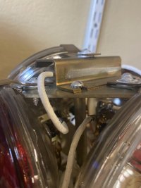
I have a federal Beacon Ray model 176 that I wanted o hook up but there are jumper wires from the bulbs that are not attached. I think it is a simple hookup but hoping someone could give me info on wiring. Also black and white wires under base. Which one Pos and which Neg. (i know this is a stupid question but wanted to know before applying power).


Thanks
 
Most likely the white is pos. and black is neg. Wait for someone who is a pro at the 176, because I just got a CTS with all black wires, and checked with the volt meter that the thickest wire was pos. and a regular black wire was ground. Confusing, I know. :lol:
 
The 175 and 176 usually have two positive connections, one labeled "W" for the white bulbs, the other labeled "R" for the red (or other color) bulbs. Some departments would install a jumper wire across the leads so that all of the bulbs would be on whenever the beacon was activated. There is a white wire leading from one terminal, and a black wire leading from the other terminal, both go to the motor to insure the motor gets power regardless of which set of bulbs were receiving power. The ground on the Beacon Ray was always through its chassis.
 
Thanks thats exactly what I was looking for. Glad I asked as I would have never know they were both Pos. As far as the jumpers wires on the bulbs, any idea?
 
Each bulb should have two wires attached to it, one wire from the top of the lamp holder assembly, the other from the bottom. There should not be any jumper wires connecting one bulb to another.
 
After looking more closely at this I realized my 2 clear bulbs only have one screw post. The others are gone so I know that is a problem. From the way it is wired I have the two reds with one wire each to a ground on the top plate and one each going to a wire coming out of center top and the other bulb has a wire coming from the base. I assume those are positives. The two clears have a wire each from the only screw post to a ground and the other bulb has a wire going to top center post. I have one wire from top post that was not connected. If someone can verify that the top center post is the positive than I know I need to get two new clear bulbs and rewire.


thanks
 
put this project away and now i am trying to get it to work again. i have the two wires from top post (positive) going to top screw on 2 bulbs. i have two ground wires from top plate going to the other terminal on bulbs. i have one bulb with a wire coming from bottom base plate (positive) and one one wire from top base plate ground to other side of bulb. that now only leaves me one ground wire from top base plate to the 4th bulb but no positive wire. am i missing a jumper or wire somewhere?
 
Here are some pics to help:
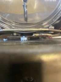
IMG_1353.JPG
The "White" (clear bulbs) are on their own circuit that is operated by a brush ring under the lamp assy.

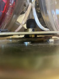
IMG_1354.JPG
In this photo, you can see the brush ring as well as the grounding nut/bolt for the bulbs. (Note the white wire coming up through the base plate.) One terminal from each bulb should be connected/grounded here.

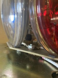
IMG_1355.JPG
This is the brush assay for the clear bulb circuit. The leads should go to the open lugs on the clear bulbs.

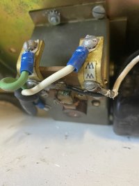
IMG_1356.JPG
The red circuit is powered like the 17, 174, 176 bulbs: the top post is hot with wires going to the open lugs on the red bulbs.

Side note: this is why it used to be a PITA to change a burnt out par36 on any BeaconRay!! Climb on the roof...take the skirt/dome off...DONT SCRATCH THE PAINT!!...unscrew the mount screw & lug screws...insert new bulb...reverse process...!!

Hope this helps!
 
thanks that helps alot. i only have one wire coming out of the bottom plate that would go to the clear bulb so i guess i would need to make a jumper wire to go from one clear to the other clear for positive?
 
@TD2162
Went through my photos but couldn’t find them…so I took some more. Hope this helps.

White lamps power brush:
43CC4F32-95FE-432A-A0EF-2A307CE3F6F0.jpeg 55316C43-98ED-486B-9A4A-6AE152F68F64.jpeg

Lamp ground lug with white power brush in background. Power connections next to motor (motor power wire connects to R terminal—red lamp power brush on the bottom of gear box):
39F92BCD-A878-4EB6-8D71-CEE4DE098606.jpeg 883A4C44-2812-47B5-9653-57DCDE0221D4.jpeg

Red lamp power wires from top of bulb assy (Under 175 tilted bulb bracket):
433C34D1-C59D-49B6-8BDB-225D517D2B88.jpeg
 
  • Like
Reactions: TD2162
@TD2162
Went through my photos but couldn’t find them…so I took some more. Hope this helps.

White lamps power brush:
View attachment 233729 View attachment 233723

Lamp ground lug with white power brush in background. Power connections next to motor (motor power wire connects to R terminal—red lamp power brush on the bottom of gear box):
View attachment 233725 View attachment 233726

Red lamp power wires from top of bulb assy (Under 175 tilted bulb bracket):
View attachment 233727
Thanks!
 

Forum Statistics

Threads
54,884
Messages
453,519
Members
19,590
Latest member
Tagg