DIY switchbox less then $20

LED

Member
Member
May 25, 2010
618
41
New England, MA
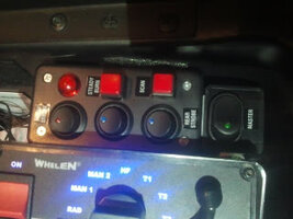
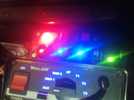
I needed a compact switchbox but could not find exactly what I was looking for. It needed to be very compact and easy to mount on the side of the center console/hump and have LED rocker switches on the bigger side. I found the following at radio shack: a 6X4X2 plastic project box (http://www.radioshack.com/product/index ... Id=2062283) for $5, and these chunky rocker switches (http://www.radioshack.com/product/index ... nSession=1) 4 @ $3. I simply drilled 4, 1/2" holes on the side of the box, and will drill another 1/2" hole in the bottom for the wiring loom to exit. Overall a simple project, looks pretty good, and is very cheap. The box is only going to run 2 pimp pods on 1 switch, a TIR4 6 head on another switch, and a 2 head Axixtech TIR LAW set on another switch. The 4th is a spare for now. In case you were wondering, I used rocker switches that mount into 1/2" holes as I find them much easier to mount.


Step 1- Assemble your gear. You will need a screwdriver with Phillips bit to close the box (not necessarily needed in making box), a drill and a 1/2" drill bit of your choice, your switches, and the box. I prefer to use the wood bit on a fast speed as it melts through plastic with ease and leaves a nice clean hole.
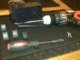

ai75.photobucket.com_albums_i301_StreetDodge_EverythingBefore.jpg


Step 2- Drill your holes. The project box has little lines used to mount things inside and I basically centered the switches inside, really helps keeping everything lined up neatly.
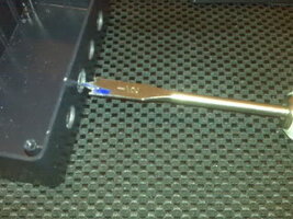

ai75.photobucket.com_albums_i301_StreetDodge_Drilling.jpg


Step 3- Mount your switches, simply screw them in the holes.
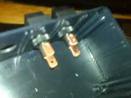

ai75.photobucket.com_albums_i301_StreetDodge_SwitchboxInside.jpg


Step 4- All done! Wire it up, mount it and your good to go. As you can see the actual box is smaller then the footprint of a dollar bill. The box has plenty of room inside for the wiring.
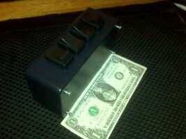

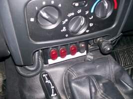
ai75.photobucket.com_albums_i301_StreetDodge_SwitchboxFinalSize.jpg
 
Very cool, I can think a few times I could have used this. I am going to make one for fun & experiment with different switches.
 
I am planning on building one of the first box shown. The first two switches will be running 1 dash light (1 LED and 1 strobe) each. Another switch will be for my CB. The fourth switch will be for future use. I am fine up through wiring the box itself. Beyond that, I'm lost. I have no clue as to what I need in order to get power to everything and the like. Any help will be greatly appreciated.


For reference, I am a volunteer firefighter which is what the lights are for.
 
wire, number of switches preffered, relays if needed, various connectors, a box to put them in and assemble.
 
I was thinking of wiring like this after looking at a few wiring setups today.


Battery + to a fuse block. Connect each switch to a single space on the block. Run the "load" from switch to a buss bar then to each piece of equipment. Then running ground from equipment to buss bar then to another fuse block then to ground on frame. Just not sure where in this to hook up the ground from the switches.
 
ff_emt_820 said:
I was thinking of wiring like this after looking at a few wiring setups today.

Battery + to a fuse block. Connect each switch to a single space on the block.


that will work


Run the "load" from switch to a buss bar then to each piece of equipment.


why? are you planning on swapping out equipment fairly frequently?


Then running ground from equipment to buss bar then to another fuse block then to ground on frame.


Way over kill. its the norm to ground equipment as close to its current location as possible. I found out with "experimentation" that if your ground is longer than the positive feeding it the equipment tends to run not at its peak capacity.


Just not sure where in this to hook up the ground from the switches.


as stated above hook the switch grounds as close to the box as possible.

I beleive i read in the chat where you and Ben E were discussing this and he advised a fuse block with both + and -. This will be good for the switch box your planning on making but do NOT run the wires from your power supply, leds, cb etc back to this panel unless you are placing all the equipment in close proximity. for example if your putting your 2/40 power supply in the trunk of your car ( you didnt specify vehicle type so im just guesstimationg your application) you shouldnt run a ground wire all the way to the switch box. ground as close to the supply as you can.


hope this helps.
 
It will be installed in a 99 Tauras wagon. I will probably end up grounding the dash LED, CB, and switches to the fuse block (will be mounted directly behind console currently in planning stages). The strobe pack will be mounted under the rear seats and grounded to a seat mounting bolt.
 
ff_emt_820 said:
.....mounted under the rear seats and grounded to a seat mounting bolt.

no, no, no...... seat bolts are horrible grounding points. you're only asking for problems if you do that.


ideally, if not running the wire back to the battery, run it to a kick panel, attaching to a green grounding bolt. if that's too much work, use a self tapping screw/bolt under a door sill or behind a plastic molding part.
 
Here is the switch box that I am constructing. It will be installed into a console (that is in planning stages).


I am using an 8" project box from Radio Shack. There is a 6-gang fuse block (that was laying around) inside the box.


I only have the power wires hooked up to the switches (no power since not installed yet) and the wire from the "load" prong on switch 1.


Grounding these is still a confusion to me.

Picture0006.jpg

Picture0005.jpg
 
you dont ground a switch box unless it has lighted swiches.
 
all switches are illuminated. i am going to use 5 switches and ground them all to what will be the empty spot on the terminal strip and from there to a good ground under dash.
 
whatevah said:
From the Jeep world, a guy (not me) used the larger RS project box to make a 7-switch box to mount above the rearview mirror. It's been pretty popular with the Jeep Cherokee offroad guys. full details: http://fitchva.com/jeep/?p=75

[Broken External Image]:http://fitchva.com/jeep/gallery/main.php?g2_view=core.DownloadItem&g2_itemId=707&g2_serialNumber=1

That looks awesome. I used to go to the junkyard to pull switch panels from wrecked conversion vans, they worked pretty good too. Most had 3 to 4 lighted rocker switches on a brushed or painted aluminum panel with a plastic enclosure.
 
Hi everybody,


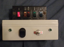
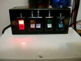
I was completing the restoration of my Wrecker AeroDynic 25RWL and noticed I could not control the turn signals. I used the "AUX" input in the old (but still functional switchbox) to light-up the D.O.T mini-bar and left-right STT red signals. I wanted to be able to play with them as a real wrecker could so I built a custom-made switchbox.


Here it is:


ai767.photobucket.com_albums_xx311_toon80_Switchbox_DSCN0342.jpg


ai767.photobucket.com_albums_xx311_toon80_Switchbox_DSCN0343.jpg


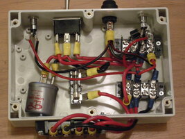
The inside has the following.


Top left and right corners have slave turn signals like your dash would.


I bought a new flasher and fused it before going in the circuit.


From the picture below, the left switch is the left/off/right turn signal controller.


The switch on the right acts as a "Hazards" light controller.


I used 2 diodes (top right corner under the wiring) to prevent back flow in the system so you can control each light individually and still override everything as soon as you hit the "hazards".


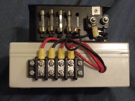
The back of the box have the standard bus-bar to connect the hot, ground, left and right signals. This was done in about an afternoon and cost me around 35$. Not too much for a fun little project. :)


When I have the time, I'll upload a clean drawing of the circuit plan. The old one has been written over many time so it's not very pretty... ;)


I hope it will help some of you who want to make their own little project boxes.


ai767.photobucket.com_albums_xx311_toon80_Switchbox_DSCN0344.jpg


Material needed was:


-1 project box, 2 switches (1 ON/OFF and 1 ON/OFF/ON), 2 diodes, 3 bus-bars, 1 flasher, 1 fuse holder, 1 fuse, a few feet of wire and the needed crimps to get all of that together. I soldered the slave turn signals. That's the only item where I needed the soldering iron. Only thing left to do would be to identify the front board to complete the "cosmetics"...


Here's a video:


ai767.photobucket.com_albums_xx311_toon80_Switchbox_th_DSCN0347.jpg


-Toon
 
unlisted said:
That would be perfect with a Microman 8" bar tucked up front/ built into the housing.. ;)

I really like that setup. I think the next install I do I am going to see how the customer likes that design and go from there.
 
This design from the Jeep world, I am currently utilizing in my Canyon. Works awesome controlling a streethawk and providing a base point for power. Only issue I have had: if you kink the CAT 5 cable, you can cause a short to another switch.

whatevah said:
From the Jeep world, a guy (not me) used the larger RS project box to make a 7-switch box to mount above the rearview mirror. It's been pretty popular with the Jeep Cherokee offroad guys. full details: FitchVA.com » Writeups » Switch Box gen IV vA

[Broken External Image]:http://fitchva.com/jeep/gallery/main.php?g2_view=core.DownloadItem&g2_itemId=707&g2_serialNumber=1
 
Here is the design I came up with when I bought my trailblazer in 06. I used this switchbox up till a week ago when I decided to make some changes. It had 4 lighted rocker switches and two momentary push buttons. Starting from the bottom of the picture and going towards the top the switches controlled the following:


contro


Red Rocker - Master Power


Green Rocker - LED Dash, Grill And Rear Headliner Lights


Red Rocker - Strobes (Clear) In The Headlights And Reverse Lights


Red Push - Controlled The Siren Tones On My Whelen Aplha12R


Black Push - Air Horn


Red Rocker - Strobes In The Brake Lights


I also used two 40A relays to power the siren, strobe power supply and all LED Lights. It helped cut down on the running of big gauge wires up to the switchbox from under the rear seat. I was abe to get all of my power from under the rear seat where if I remember correctly is where the ECM is mounted which has a wire direct from the battery.


All parts used in making the switchbox were bought at radio shack.


40600112.jpg-
 
this is one I have recently made. The round 1/2' hole mount ones are simple but I wanted lower profile. The switches are $2 ea at walmart but require more install time. Overall I am happy with the results.

IMAG1740.jpg
 
That looks very clean ^ Do you ever hit the switches when you are getting in/out of the car?
 
Jennifer Rose Towing said:
this is one I have recently made. The round 1/2' hole mount ones are simple but I wanted lower profile. The switches are $2 ea at walmart but require more install time. Overall I am happy with the results.

Just curous as to how you made the holes for your switches. I have the same wally world switches the hole is 1/2in wide by about a 1 1/4 long. What is the best way to make the openings for the switches. Thanks Randy
 
One way is to drill a hole slightly smaller than the width of the switch the use a small file or exacto knife to make the hole the correct size.
 
Here are a couple photo's of my DIY switchbox. Using a Radio Shack project enclosure. The top switch looks a bit off, but they are all in line, it is just turned a bit to the left. I threw some Whelen switchbox legends on there just for the heck of it. I did not have any that said front or rear flash, so I used front and rear strobe. It is located in the console of my Suburban. I plan on taking install picks later down the road.


3 lighted rocker switches activate the following:


Red: (top) Activates a "Priority" pattern on my WL28.


Blue: (middle) Activates all front warning lights.


Blue: (bottom) Activates all rear warning


Green: Master power for the red and blue switches.


Square switches:


Steady burn: Activates steady burn feature of the WL28.


Scan: Pattern select for the WL28


The red indicator is for the "Steady Burn" switch, since it is not lighted.


I will try to take a couple better pictures.


ai989.photobucket.com_albums_af15_asp3760_2011_10_03220518_1.jpg


ai989.photobucket.com_albums_af15_asp3760_2011_10_03220531_1.jpg
 
Thanks for the Idea of this switchbox! I made my own, soldered everything, then just put some white electrical tape over the connections to make sure nothing made contact with something it shouldnt make contact with.. only put 2 switches and will add more later on. the switches arent perfectly aligned, but it was the first time I've tried it for myself. DEFINITELY will do again

1.jpg

2.jpg
 
Here's a trick to getting all the switches nicely lined up and evenly spaced out on the project box.


Get some masking tape. I like the blue painter's stuff because it doesn't leave any adhesive residue when you peel it off, even if it has been on for quite a while. It is also available in different widths.


Completely cover the front (and even the sides if you like) with the tape. Then, using a square and straight edge, mark your switch holes as precisely as possible. Use the straight edge to mark lines that run straight and even across the length of the panel face.


I like to use the Ultra Fine Point Sharpies for this layout work.


The Bob Vila rule applies here: "Measure twice, cut once."


Once you have everything laid out to your satisfaction, you can begin to drill your holes. As already pointed out, stay well inside the lines, and then use a file or exacto knife to open the holes up to final size. It is always better to start undersize and bring the holes to full size gradually, checking your work with a switch as you go.


When you are nearly done, use an emery board to clean up the holes and remove any burrs.


Dry assemble all the switches and lights. Step back and see how it looks. If necessary, tweak where needed.


Now you can remove the masking tape. Leaving the tape on while you fabricate the box will protect the surface from dings and scratches.


One final note, if you don't need an actual box for your switches, ABS plastic sheets are readily available and just as easy to work. Lexan works well, too.
 
I've used the same "trick" on several installs over the years.


I use two switches for most of my stuff - one to run all front warning, and one for the siren power. The smallest RS project box, turned on it's side, with the RS 30A oval switches installed in the long / thin side, has worked great. The 30A lighted oval switches are pretty good quality and I have used them for stand alone in-dash installations without the project box, too.


I don't have any current pictures of old installs, but on my old 2001 and 2002 S-10s, the switchbox was 3M dual locked to the right side of the dual cupholder that was situated in the U shaped cutout in the front of the bench seat, with wiring exiting under the seats. It was very unobtrusive and easy to use.


On my current 2007 Civic, the switchbox is mounted in a recess near where the driver's left knee is, with wiring exiting out the back side into the dash.


[Broken External Image]:http://i136.photobucket.com/albums/q189/MeefZah/Miscellaneous Stuff/IMG_1913.jpg


[Broken External Image]:http://i136.photobucket.com/albums/q189/MeefZah/Miscellaneous Stuff/IMG_1914.jpg
 
MeefZah said:
I've used the same "trick" on several installs over the years.

I use two switches for most of my stuff - one to run all front warning, and one for the siren power. The smallest RS project box, turned on it's side, with the RS 30A oval switches installed in the long / thin side, has worked great. The 30A lighted oval switches are pretty good quality and I have used them for stand alone in-dash installations without the project box, too.


I don't have any current pictures of old installs, but on my old 2001 and 2002 S-10s, the switchbox was 3M dual locked to the right side of the dual cupholder that was situated in the U shaped cutout in the front of the bench seat, with wiring exiting under the seats. It was very unobtrusive and easy to use.


On my current 2007 Civic, the switchbox is mounted in a recess near where the driver's left knee is, with wiring exiting out the back side into the dash.


[Broken External Image]:http://i136.photobucket.com/albums/q189/MeefZah/Miscellaneous Stuff/IMG_1913.jpg


[Broken External Image]:http://i136.photobucket.com/albums/q189/MeefZah/Miscellaneous Stuff/IMG_1914.jpg


Nice job... :thumbsup: I actually plan on using the cubby hole where you have the Power Mirrors and Fog Light switch... I'm going to be getting an OEM fog light kit with the switch plate for that area, then i'm gonna order either another factory sty switch to run everything, or get a couple switches to separate some stuff...
 
Jennifer Rose Towing said:
this is one I have recently made. The round 1/2' hole mount ones are simple but I wanted lower profile. The switches are $2 ea at walmart but require more install time. Overall I am happy with the results.

I like these but the lights inside of them burn out within a week.
 
Steve0625 said:
Here's a trick to getting all the switches nicely lined up and evenly spaced out on the project box.

Get some masking tape. I like the blue painter's stuff because it doesn't leave any adhesive residue when you peel it off, even if it has been on for quite a while. It is also available in different widths.


Completely cover the front (and even the sides if you like) with the tape. Then, using a square and straight edge, mark your switch holes as precisely as possible. Use the straight edge to mark lines that run straight and even across the length of the panel face.


I like to use the Ultra Fine Point Sharpies for this layout work.


The Bob Vila rule applies here: "Measure twice, cut once."


Once you have everything laid out to your satisfaction, you can begin to drill your holes. As already pointed out, stay well inside the lines, and then use a file or exacto knife to open the holes up to final size. It is always better to start undersize and bring the holes to full size gradually, checking your work with a switch as you go.


When you are nearly done, use an emery board to clean up the holes and remove any burrs.


Dry assemble all the switches and lights. Step back and see how it looks. If necessary, tweak where needed.


Now you can remove the masking tape. Leaving the tape on while you fabricate the box will protect the surface from dings and scratches.


One final note, if you don't need an actual box for your switches, ABS plastic sheets are readily available and just as easy to work. Lexan works well, too.

Good tips for layout...


I use a cordless dewalt drywall cutout tool for cutting project boxes, works great, very quick and painless
 

Forum Statistics

Threads
54,701
Messages
452,860
Members
19,496
Latest member
darkdreamer3