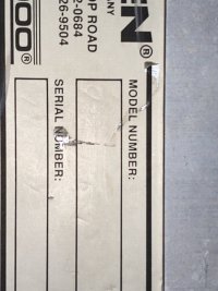
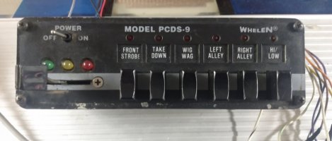
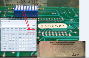
For what it's worth, I have a PCDS-9 and a Whelen "Serial Controller Receiver" board (part #01-0266995-00C) and spent some time trying to make sense of the communications between the two.
Looks like they talk at 4800 bps,8,1,N though I'm not sure of the electrical format (i.e. definiteley not RS484, don't think its straight RS232).
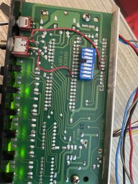
For now, I just bypassed that detail and soldered a wire between PIN #29 of the MCU on the control board ("RDI on the 68HC7058N data sheet") and connected it to pin "D13" on a "SparkFun RedBoard" (Digikey part #1568-1768-ND).
For development, I use the Arduino IDE available at
www.arduino.cc/en/software
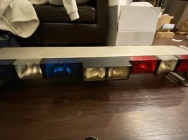
With the code attached, I got the alleys/takedowns/scenelight and rear-flashers to work. I don't have a Diagnostix lightbar to test with so I can't observe the correctness of strobe (or other) behaviors - but I did measure voltage changes on the strobe connector port and they seemed to correspond with messages associated with the 4-way slide-switch messages.
I'll be digging a lot more into the message details and electrical details and ideally, be able to offer-up a "how-to" so anyone can build their own controller for "Diagnostix" lightbars.
For now though, for those with a little appetite for electrical adventure, this might help get you started.
For the record, the MCU in my PCDS-9 is labeled "OHIO Xmtr" which I assume means it is compatible with lightbars shipped to OSP.
The Serial-Receiver board I have had a Whelen repair ticket attached indicating it came from Massachusetts "Department of Public Safety" on the account of "MHQ", one of the big municipal supply houses in MA.
PS: Merry Xmas!!! ELB rox! Love the snow falling all over the page right now!