Federal Model 28 wiring help please........

Captain014

Newbie
New Member
May 24, 2010
11
0
Canada - New Brunswick
I'm going to put a Model 28 siren on one of our trucks. I'd like a foot switch on both the driver side and passenger side, although driver side only would work as well. Can someone please tell me how it would be best to wire it up? I know big gauge wires to the siren from the battery, it should ground itself out on the frame, but I've seen a relay being used.


And, a source for a foot switch too, please.


Thanks!


Andrew
 
You will want to use a solenoid for the foot switch. This ensures that the foot switch switches only a relatively small current, and that the high current stuff stays between the battery and the siren itself, and as short as possible.
 
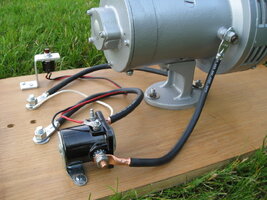
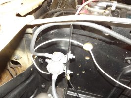
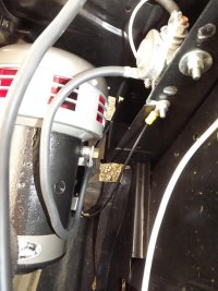
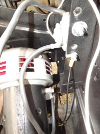
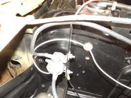
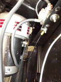
It should look similar to this. I have my Model 28 wired up to connect my power cables to the bolts. You would substitute the small push button for a foot switch.


ai288.photobucket.com_albums_ll196_GSPD44_Sirens_IMG_0405.jpg
 
That relay is a starter relay. you can get them at ANY parts store, for around 10.bucks..


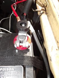
+ from battery(big lug) --->Relay--->to siren +(other big lug)


little lug gets a power when the switch is depressed(closing the relay, and powering the siren!)
 
Back in the day I wired mine with a starter relay also, and never had any problems. But somewhere on the old board it was mentioned that starter relays are meant only for brief intermittent use, and recommended some other type of heavy duty relay. Don't remember what.
 
You are looking for a "continuous duty solenoid" not a relay. What is pictured is probably more correctly called a starter solenoid. A solenoid functions in the same way as a relay, but can generally undergo a much higher current.


Solenoids are rated by their duty cycle (continuous, or a percentage of on time), and the number of amps the can safely switch. Look to spend between $15-$30 for a continuous duty solenoid that can switch, what, 50 amps or so.
 
shues said:
You are looking for a "continuous duty solenoid" not a relay. What is pictured is probably more correctly called a starter solenoid. A solenoid functions in the same way as a relay, but can generally undergo a much higher current.

Solenoids are rated by their duty cycle (continuous, or a percentage of on time), and the number of amps the can safely switch. Look to spend between $15-$30 for a continuous duty solenoid that can switch, what, 50 amps or so.

continuous duty..... is key.
 
Guys be careful on these "continuous duty solenoids/relays" for mechanical siren use. Most have contacts rated at only 85 amps on make. Starter intermittent relays have contacts rated at 750 amps on make. You could probably get by with a continuous duty relay with the Model 28 but I sure would not use one on a larger siren such as a Q which can pull 200+ amps on startup unless the contacts are rated for at least 200 amps. Pulling 750 amps thru a relays contacts can only be done for a short time before a cool off period but pulling 100 amps thru the same relay you do not have much to worry about. You can look at the specs of the various Cole Hersee relays here: http://www.colehersee.com/catalog_top/index.htm
 
Henry455,


Good recall!


I remember using Ford starter relays that were rated for 80 amps for the Model 28. By having it fused right, someone who might "ride" the siren might first burn out a solenoid, but not a siren. I also recall using big cartridge type fuses (like two 75 amp fuses in series) to fuse the thing. We modified a floor mounted headlight dimmer switch to use as a momentary floor switch. And, on smaller vehicles, the siren was activated by selecting a two way selector switch and using the horn ring.


Wiring a Q was a different matter, and we used the Federal parts kit.
 
This is what some of the current electro-mechanical siren manufacturers recommends.


The recommended solenoid for B&M sirens is the Cole-Hersee 24059.


The foot switches recommended are Cole-Hersee 9183 and Linemaster 491-S.


The recommended solenoid for Screaming Eagle sirens is Cole-Hersee 24117.


The foot switch recommended is Linemaster SP491-SB1.


B&M sirens are the more current consuming ones and will exceed the model 28 current draw.
 
Hey guys- looking to reserective this to some degree as I am looking to install one. Am interepreting this correctly as the POS lead from the battery will get connecter to the one side of the solenoid that goes to the terminal on the wood block? Also, do the 2 leads on the switch both go to the center 2 terminals, one on each side? The photo is a bit blind in that regard. Thans!

shues said:
You will want to use a solenoid for the foot switch. This ensures that the foot switch switches only a relatively small current, and that the high current stuff stays between the battery and the siren itself, and as short as possible.
IMG_0405.jpg
 
TonyT said:
Am interpreting this correctly as the POS lead from the battery will get connected to the one side of the solenoid that goes to the terminal on the wood block?

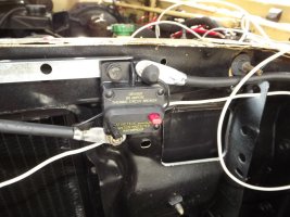
Yes. However, there should be a (big ass) fuse or breaker between the battery and the terminal.

TonyT said:
Also, do the 2 leads on the switch both go to the center 2 terminals, one on each side?

No. One wire from the switch goes to the solenoid coil. The other switch terminal should go to battery +, with a 10 A or so fuse. The remaining solenoid coil terminal goes to ground (the white wire in the pic).
 
MtnMan said:
Yes. However, there should be a (big ass) fuse or breaker between the battery and the terminal.

I called FS about this, and they recommended at least a 75 AMP protection device. Personally I used a 100 amp on my setup. It's all short wire runs with large awg wire so I'm not too concerned that I may have a slightly too large breaker.
 
Just a heads up that many of the older starter solenoids ground one side of the coil when mounted but still have two small wire lugs. These lugs are usually labeled S and I for Start and Ignition and were used in older cars to bypass the ignition ballast resistor while cranking the starter. Placing positive and negative on this type solenoid's smaller lugs will likely result in a short as both are hot when the solenoid is activated. Just a F Y I to check what you have first. The type solenoid I describe went in earlier cars and trucks back when distributors had points and condensers and are still carried by parts stores everywhere. These solenoids will work fine if wired for the siren application correctly, ignoring and capping the I terminal, using one fused, switched positive wire to trigger (close) the solenoid from the S terminal.


And Henry 455, great info on the inrush amp capacity of continuous duty solenoids I was not aware of. Thanks!!
 
cmb56 said:
This is what some of the current electro-mechanical siren manufacturers recommends.

The recommended solenoid for B&M sirens is the Cole-Hersee 24059.


The foot switches recommended are Cole-Hersee 9183 and Linemaster 491-S.


The recommended solenoid for Screaming Eagle sirens is Cole-Hersee 24117.


The foot switch recommended is Linemaster SP491-SB1.


B&M sirens are the more current consuming ones and will exceed the model 28 current draw.

The B&M will draw more current than the Eagle siren because the Eagle has a much smaller motor. But B&M's current draw is far less than the Q or the 28.
 
TonyT said:
I picked up the 24059 thinking it was adequate. Did I purchase in error?

That 24059 will work fine. I am running two Federal C-5 from one 24059 and two more (C-4 and Superchief) from an eight dollar lawnmower solenoid from the auto parts store. No problems....to report, other then I live dangerously and only use the sirens occasionally, but I feel confident in posting that the 24059 will hold up to one siren in actual service without an issue. The solenoid in above pic is one of those I posted of, the second smaller terminal (I) is not used in this application as it goes hot with the first one. The white wire is grounded to solenoid frame, out of view. See, I'm not nuts, just crazy.


:hissyfit:
 
MtnMan said:
Yes. However, there should be a (big ass) fuse or breaker between the battery and the terminal.


No. One wire from the switch goes to the solenoid coil. The other switch terminal should go to battery +, with a 10 A or so fuse. The remaining solenoid coil terminal goes to ground (the white wire in the pic).

Please clarify; the white wire looks to be coming from the mounting hole on the solenoid, not the other small lug?
 
That's the way I see it too. The solenoid in above pic is one of those I posted of, the second smaller terminal (I) is not used in this application as it goes hot with, but is isolated from the other terminal (S). The white wire is grounded to solenoid frame, out of view.
 
Torpedo said:
That's the way I see it too. The solenoid in above pic is one of those I posted of, the second smaller terminal (I) is not used in this application as it goes hot with, but is isolated from the other terminal (S). The white wire is grounded to solenoid frame, out of view.

Yup, I stand corrected.
 
Most 4 post solenoids are isolated= load (big posts) are separate circuits switch (little posts). A simple way to switch is to take + from battery side (large post) and jump to small term. 2nd small term run to switch(es), one wire and ground. 2nd large post to load. When switch(es) are engaged, they complete the loop for the circuit, engaging load and only need one feed wire.
 
foxtrot5 said:
I called FS about this, and they recommended at least a 75 AMP protection device. Personally I used a 100 amp on my setup. It's all short wire runs with large awg wire so I'm not too concerned that I may have a slightly too large breaker.

Checked out the video on the pickup but didn't see or hear the 28. What is that bright-assed steadyburn red light? Wow!
 
Skip Goulet said:
Checked out the video on the pickup but didn't see or hear the 28. What is that bright-assed steadyburn red light? Wow!

I still need to update the video with the 28 rolling but right now, I've got the interior bar sitting on my kitchen table and most of the wiring is disconnected because I'm waiting for my Feniex 4200 to arrive so I can finish my power distribution and flasher board. The steadyburn in the center of the windshield is a Whelen Dual Avenger.
 
foxtrot5 said:
I still need to update the video with the 28 rolling but right now, I've got the interior bar sitting on my kitchen table and most of the wiring is disconnected because I'm waiting for my Feniex 4200 to arrive so I can finish my power distribution and flasher board. The steadyburn in the center of the windshield is a Whelen Dual Avenger.

I've never been much on steady burns, but that one is bright. I've never seen an Avenger. Does it have flash patterns as well?
 
Skip Goulet said:
I've never been much on steady burns, but that one is bright. I've never seen an Avenger. Does it have flash patterns as well?

Plenty of em. But I figured I had enough flashing lights and after using it, I wouldn't NOT have a steadyburn light on my setup.
 
foxtrot5 said:
Plenty of em. But I figured I had enough flashing lights and after using it, I wouldn't NOT have a steadyburn light on my setup.

I have an STL visor light r/r on my POV and it has steadyburn, but on one side only. I've tried it that way and it seems to work o.k., but it's nowhere near as bright as that Avenger.
 
Skip Goulet said:
I have an STL visor light r/r on my POV and it has steadyburn, but on one side only. I've tried it that way and it seems to work o.k., but it's nowhere near as bright as that Avenger.

Yeah, right now, I'm running the truck without the visor bar in it and I still have NO problems clearing traffic.
 
MtnMan said:
Yup, I stand corrected.

OK, got it all wired up but I may have the solenoid wired backwards, is that possible? I saw no markings on the leads. Nothing happens when powered up. Will run when I bypass.
 
Can you post photos of how it's wired up?
 
TonyT said:
OK, got it all wired up but I may have the solenoid wired backwards, is that possible? I saw no markings on the leads. Nothing happens when powered up. Will run when I bypass.

Hi Tony. Try grounding the solenoid frame and using a short + jumper to one, then the other small post, one at a time. If no audible click is heard with either then try grounding one small post (doesn't matter which) and apply positive to other small post. If still not activating then I am guessing an open coil in that solenoid. It can happen, they mass produce 100+/- a day and glitches happen. DT
 
foxtrot5 said:
Can you post photos of how it's wired up?

I agree. I'd like to see how you have it wired. Dennis may be right....something in the solenoid somewhere. Even without it being wired to the siren you should hear the audible click when power is put to it. Many years ago I took one of our ambulances to an automotive electrical shop (you'd think they'd know what they were doing, and I'd used that shop in the past) to have a siren mounted on the roof. I had them replace the old spring-loaded footswitch with a dimmer switch hooked to a solenoid underhood. Apparently the guy who did the work didn't know what he was doing. Because with using a dimmer switch it's push on and push off for the siren, I had them also install a "safety switch" on the dash in case someone taller than me (which means everyone!) might step on the button accidentally. But whe you flipped the toggle switch on it engaged the solenoid by itself. I tried the siren to make sure it was actually hooked up and it rolled over; but somehow the miswiring ended up frying the brushes in the siren motor. The owner of the shop checked it out and found out what the guy had done and fixed the problem and replaced the siren brushes at no extra cost to us. Worked like a charm after all that. :yes:
 
I have grounded the solenoid. I wont be able to get pics until later in the week as I left the car for some further installs. There was no click and I was hoping the large studs may have just been reversed. Will advise guys, thanks.
 
TonyT said:
I have grounded the solenoid. I wont be able to get pics until later in the week as I left the car for some further installs. There was no click and I was hoping the large studs may have just been reversed. Will advise guys, thanks.

With the solenoid in front of you and the front of the solenoid facing away from you, the large stud on the left is for the siren, the right stud goes to the battery. If it has the two small terminals on top, the right goes to battery and the left to your switch. Some of the older solenoids were grounded-types, with a single small stud on top. Everything is like I describe above, but the small stud goes to switch and from switch to ground to make contact. That type is still used where a horn-ring conversion is used.
 
TonyT said:
What of the white wire for the switch?

OK, Tony. The small terminal on the left goes to switch, and from switch to hot. The small right terminal goes to hot, so you can run a very short wire from it to the large stud on the right that goes to battery.


I was just re-looking at that solenoid. The picture is a bit blurry. If you have just a single terminal on top, it still goes to switch but from switch to ground.
 

Forum Statistics

Threads
54,701
Messages
452,862
Members
19,496
Latest member
darkdreamer3