You are correct At 6vdc it supplies constant current when activated.
My tester with direct 6vdc
View attachment 244118
My tester when hooked to the socket of the device at 6vdc and "mercury switch" activated
View attachment 244117
With the device powered by 6V the socket gets the full 6v when the low voltage mercury switch is closed.
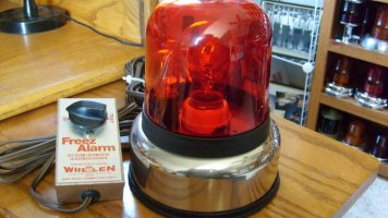
Now I am left wondering what bulb it used and why bother with this circuitry at all? Could you not just use the switch and a 6 volt bulb? What is the circuitry gaining?
The voltage going through the mercury switch is approx. 1-1.5 vdc. The circuit board is essentially a relay switching a 6 volt load with low voltage. So we have a float with a low voltage mercury switch inside that illuminates a 6vdc lamp when lifted into the closed position. The circuit is really a slightly more complex low voltage switching relay using transistors, a capacitor, and resistors to trigger a 6v lamp with a low voltage switch. This was cool to figure out, but the kid in me wanted it to blink, although the idea behind the float probably make more sense not blinking.
Also, I need to remember to use
this resistor color code tool too.
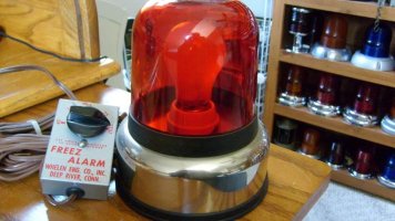
The lamp holder looks like BA9 based on the measurements, the bulb shards and base were consistent with that lamp type, and the base looked a lot like
Lamp Type: T2-1/2 Miniature
Volts: 6V, Watts: 0.84W
which would be a .14 amp draw, well within what this is putting out.