Whelen Need help with Whelen UPS 64C

TXDPSCJ

Member
Aug 6, 2023
65
14
NJ
Hi all,

So I was not sure where to post with the new site format… vintage or modern…

My car is an Ex TX patrol unit (year 93)… vintage, but still modern? LOL…

Anyhow, it is set up for the Whelen MicorMax Red/Blue Strobes at the front of the vehicle. These strobes are controlled by a Whelen UPS 64C. The strobes were 100% operational without issues, until today.

Nothing has been changed with the install set up or anything else (been working for over a year now without issue).

Today at a car show we had the strobes on and running - about 1hr into the show, the strobes stopped working. I also didn’t hear that distinct noise (cricket chirping??) that the Whelen UPS makes when it’s on.

I come home try to diagnose and am not sure what to look for or how to diagnose since nothing changed in the setup.

When I turn the strobes on now, I can hear the MicroMax distinct noise at the front of the car at each strobe (the “click” for the pulsating at each strobe) and the strobes are very dimly lit/flashing (not super bright as they were normally). The Whelen UPS isn’t making any noise like it normally did…. When I flick the lights on from the Code 3 control box in the car, I hear a click on the Whelen UPS but not that distinct chilling noise.

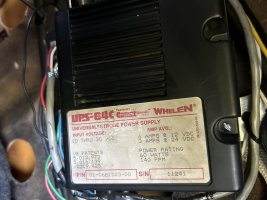
Can someone please provide me with some guidance? I’m including an image of the UPS:
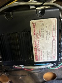
IMG_7017.jpeg

I also checked the fuse at the UPS 64C and all fuses at my distribution strip that runs all the auxiliary equipment - there are no blown fuses at all anywhere…

Also to note - this box and strobes were installed by a prior owner - and again worked 100% when he had the car and when I bought the car over a year ago… today is the first time the stores stopped working.

Do these boxes just die? Or what should I be looking for?
 
Last edited:
Do these boxes just die? Or what should I be looking for?
They can but strobe tubes are more likely as they do wear out. I would go over the wiring and manual too just to satisfy my mind. Strobe tubes can be hooked up incorrectly but still run, just reduces their life. It is possible that the power supply is overdriving the tubes. I do not remember tge wiring on that one but if they are hooked to a channel designed to run 4 strobes but you are only running 2 you could be overdriving them. Do you by chance have another pair of strobes or different power supply you could test with?
 
  • Like
Reactions: TXDPSCJ
Upvote 0
They can but strobe tubes are more likely as they do wear out. I would go over the wiring and manual too just to satisfy my mind. Strobe tubes can be hooked up incorrectly but still run, just reduces their life. It is possible that the power supply is overdriving the tubes. I do not remember tge wiring on that one but if they are hooked to a channel designed to run 4 strobes but you are only running 2 you could be overdriving them. Do you by chance have another pair of strobes or different power supply you could test with?

Thanks for the reply. Nope, I don’t have any other strobes or power supply. The MicroMax and the UPS 64C were with the patrol car when I got it from the prior owner.

Everything worked fine, up until today…. LOL.

Do you need better pics of the UPS 64C? I don’t even have any owners manual for the strobes or the UPS.
 
Upvote 0
I don't care to spend the time going over the manual. You can find it online and would need to verify with yours that the wiring and number of heads required is correct. Statistically the strobe tubes will need to be replaced long before the power supply but it's all old stuff so could easily be either.
 
  • Like
Reactions: TXDPSCJ
Upvote 0
Is the strobe power supply installed with its back flat against a substantial piece of metal? The requirement to sink the heat generated by a strobe power supply is often overlooked. Failure to disperse excess heat can lead to premature failure of a strobe power supply.

0FAjiXt.png


Source: https://www.whelen.com/wp-content/uploads/2020/08/13290.pdf
 
  • Like
Reactions: TXDPSCJ
Upvote 0
I had a UPS64C that behaved the same way...specifically, you could hear the "clicks" of each strobe flash and even see a tiny little arc within the flash-tube...but no actual brilliant flash as expected.

The problem is that the primary inverter is not generating energy to the primary capacitors. In my case, the root-cause was that the one of the legs of the transformer's solder pad had electrically separated and simply needed to be re-soldered.

There are certainly many other reasons the primary inverter can fail, however. But maybe if you're lucky, it just might be a cold solder joint along the primary inverter path.

The fact that you hear the "clicks" and see the tiny arc in the tube means all the timing and secondary inverter are working fine.

My $0.02
 
  • Like
Reactions: TXDPSCJ
Upvote 0
Thanks for the replies, the PDF link to the manual, and the tips, appreciate it!!

Also to note, the UPS 64C is only controlling the (2) Whelen MicroMax (1 red, 1 blue). Based on the PDF link supplied, I will check the configuration of the plugs from the MicroMax harnesses to the UPS. I believe the install and plug/harness to be correct as the prior owner was an IL Officer and he had a knowledgeable fleet liaison do the install (restoration of equipment back into the vehicle).

When we got home from the show last night, with the car in the garage and when I powered on the MicroMax’s again, in the garage I could see the faint strobe flashing and hear the “pulsating clicks”, but out in the bright sun at the show and all the noise (music/people/nearby traffic) I could not hear the clicks. There is deifinitely no “chirps” coming from the UPS.

To answer the question about the UPS, it is installed in the trunk of the vehicle on the back “X” cross bracing that is there for the rear seat. So the image so the unit I supplied earlier in this thread is what you see when looking into the trunk (the label side (top) is facing the rear taillight panel). It’s not near any heat or moisture and trunk compartment is empty with nothing up against or blocking the UPS.

The other question I have with the UPS box is, if I have to replace the UPS 64C, what is the difference between the 64C and the 64LX? The images of them look pretty similar; I’m guessing there’s a difference internally?
 
Upvote 0
UPS64XL is slighter more modern electronics (a bit more powerful at 75 watts and three possible flash patterns). I believe it is a quite worthy alternative.

So is the UPS64LXA with even more modern electronics for the time (microprocessor controlled) and introduced "scanlock" wire that allowed you to select one of ten possible flash patterns:

LX data sheet
LXA data sheet
 
  • Like
Reactions: TXDPSCJ
Upvote 0
Thanks for the responses. I do have a few more questions:

I checked all of my wiring - nothing has changed since I had purchased the car and there’s no issues with any of the wiring I can find (front to rear back to the UPS 64C).

I also pulled the Code 3 switch box, no issues with the wiring inside the switch box (ie: no wires off themselves and no contacts touching each other that wouid create a short). I also do not have any blown fuses at my fuse block in car, the fuse block for the equipment or the single fuse located on the 64C.

At this point, I’m going to say that due to the age of the UPS 64C, it most likely has some internal issue like @RS485 mentioned and experienced with one of his boxes as noted above in this thread. My outage is exactly the same as what @RS485 explained. I do see faint strobe pulses inside the red and blue strobes, so the bulbs in each of the MicroMax are functioning but just not at full capacity.

I’ve started looking for a replacement box. I mentioned previously, I’ve seen the 64LX (and the LXA) and I know these are a compatible swap to the 64C, but last night in my searches I found there is the “Competitor Series CPS660”. This CPS660 looks similar to the 64C, 64LX and 64LXA.

Can anyone tell me if the CPS660 is still a universal power supply and/or is this the newest version of the old 64C? Is this ok to use also, or not?

Here’s the image of the label on my UPS 64C:
IMG_7017.jpeg

I’ve tried comparing the Whelen PDF’s on each box, but I’m not familiar with the boxes enough to say that a CPS660 would be ok or not to use in place of a 64C…

Should I just replace the 64C with another 64C or 64LX? I don’t need anything fancy, just a matched box to get me up and running again.
 
Upvote 0
The CSP series are budget-minded. Rather than the beefy metal box of USP's, it is plastic so this leaves the capacitors more room to heat up (an enemy of strobe power supply longevity).

It is microprocessor-controlled and is of the LXA era. (IIRC, both use the same PIC16F628 microprocessor).

The LXA (maybe LX too) have failed tube detection. if the power supply senses the capacitors didn't discharge during a flash, capacitor-charging is scaled back so as not to drive the surviving tube(s) into the ground.

That said, I think the CSP660 is a compatible and acceptable alternative for a show piece.
 
Upvote 0
UPDATE:
So after much thought based on the replies, I procured another 64C and swapped my original with the new (used) unit and we have LIGHTS again!! Awesome.

Thank you for ALL of the replies on here - you all are the best and extremely helpful!! I went with another 64C because it was what was in the vehicle and I wanted to keep things as they were; if this one goes out in the future, then I know I have other options based on the responses here. Again, many thanks!

—-

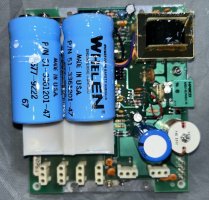
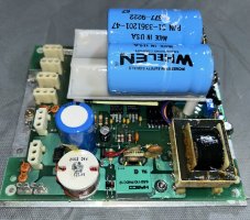
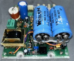
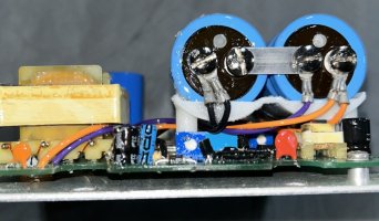
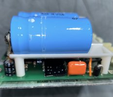
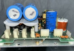
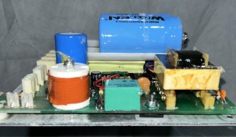
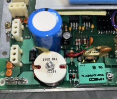
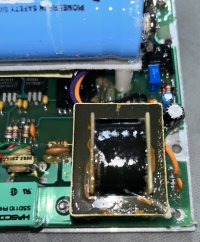
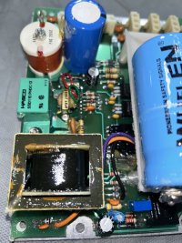
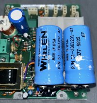
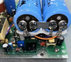
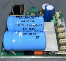
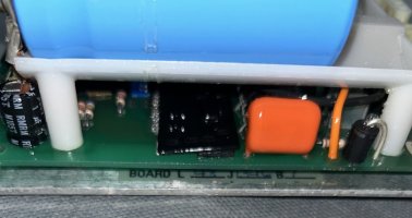
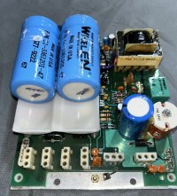
I have pulled the lid off the original 64C, and this is what is under the lid. Has anyone attempted repair of one of these ever - OR can possibly tell me what to look for as far as what on the board may be bad? Any good electrical gurus? I know not to touch the caps, so I’m being very careful. It has not had power to it since I created this original post, so I’m sure the caps are discharged by now - but still being cautious.

IMG_7119.jpegIMG_7120.jpegIMG_7121.jpegIMG_7122.jpegIMG_7123.jpegIMG_7124.jpegIMG_7125.jpegIMG_7126.jpegIMG_7127.jpegIMG_7128.jpegIMG_7129.jpegIMG_7130.jpegIMG_7131.jpegIMG_7132.jpegIMG_7133.jpeg
 
Upvote 0
First, the patent closest to describing the electronics here is:
The inventor "James L. Stopa" is the father of this power supply!

You'll have to dismount the board from the base plate and get a good look at the underside.
Given the symptom you described (everything working in the sense of producing tiny little flashes, streamers within the tubes, but no actual robust strobe flash), I think the problem is that the primary inverter isn't working.

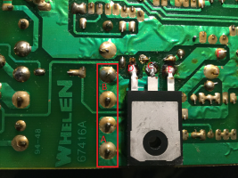
I don't have a UPS64C handy but it should look something like this:

1731835209499.png

The theory of it is this:
Current comes from the +12VDC into transformer coils at (A).
This current leaves the coils via (B) traveling through the solder trace to (C) which is the "DRAIN" as described in the MOSFET device data sheet here:
When this device is switched on, current travels across it to GND at point (D) or the "SOURCE" pin of the device.

(E) is the MOSFET "GATE". This is the control voltage that switches the MOSFET device on/off. It is this rapid switching on and off, that creates the high voltage across the secondary transformer windings, that is accumulated in the big blue primary capacitors that produces the expected bright flash.

In my UPS64C's case, at points (A) or (B), the transformer legs weren't making reliable contact with the solder around them and all I had to do was get 'em good and hot again to remelt the solder to make contact.
IIRC, it was actually kind of hard to recognize the problem... the solder itself looked fine. I had to really zoom in to see the gaps between the transformer legs and solder "mounds".

If that's _not_ the problem, then the next diagnostic tests are:
1. check the resistance between the "SOURCE" pin on the MOSFET and GND. It should read 0 ohms.
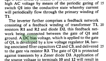
2. (be careful) with the UPS64C powered up and enabled, measure the VOLTAGE between the MOSFET's "GATE" pin and GND. It should be somewhere around +4-5VDC. This is the "DC bias voltage" described in the patent here:
1731836841349.png

Hope this helps...this is where I'd start looking if I had the device in front of me.

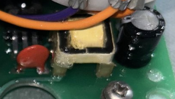
Indecently, here's the secondary inverter in the UPS64C:
1731837207245.png
its not described in the patent but it what is producing the faint flashes in your UPS64C. It's purpose to make sure the tubes flash even if the supply voltage is significantly less that +12VDC. It's up to the primary caps/inverter to produce the "current" for a bright flash, but it's the secondary inverter's job to "blaze the trail" in the tube even under adverse circumstanced...cool!

Be safe and good luck!
 
Last edited:
Upvote 0
First, the patent closest to describing the electronics here is:
The inventor "James L. Stopa" is the father of this power supply!

You'll have to dismount the board from the base plate and get a good look at the underside.
Given the symptom you described (everything working in the sense of producing tiny little flashes, streamers within the tubes, but no actual robust strobe flash), I think the problem is that the primary inverter isn't working.

I don't have a UPS64C handy but it should look something like this:

View attachment 253377

The theory of it is this:
Current comes from the +12VDC into transformer coils at (A).
This current leaves the coils via (B) traveling through the solder trace to (C) which is the "DRAIN" as described in the MOSFET device data sheet here:
When this device is switched on, current travels across it to GND at point (D) or the "SOURCE" pin of the device.

(E) is the MOSFET "GATE". This is the control voltage that switches the MOSFET device on/off. It is this rapid switching on and off, that creates the high voltage across the secondary transformer windings, that is accumulated in the big blue primary capacitors that produces the expected bright flash.

In my UPS64C's case, at points (A) or (B), the transformer legs weren't making reliable contact with the solder around them and all I had to do was get 'em good and hot again to remelt the solder to make contact.
IIRC, it was actually kind of hard to recognize the problem... the solder itself looked fine. I had to really zoom in to see the gaps between the transformer legs and solder "mounds".

If that's _not_ the problem, then the next diagnostic tests are:
1. check the resistance between the "SOURCE" pin on the MOSFET and GND. It should read 0 ohms.
2. (be careful) with the UPS64C powered up and enabled, measure the VOLTAGE between the MOSFET's "GATE" pin and GND. It should be somewhere around +4-5VDC. This is the "DC bias voltage" described in the patent here:
View attachment 253379

Hope this helps...this is where I'd start looking if I had the device in front of me.

Indecently, here's the secondary inverter in the UPS64C:
View attachment 253380
its not described in the patent but it what is producing the faint flashes in your UPS64C. It's purpose to make sure the tubes flash even if the supply voltage is significantly less that +12VDC. It's up to the primary caps/inverter to produce the "current" for a bright flash, but it's the secondary inverter's job to "blaze the trail" in the tube even under adverse circumstanced...cool!

Be safe and good luck!


Wow great links, info and tips to check out - thank you! Yep, I believe based on your earlier response in this thread that this original power supply has the same issue as yours did with the type of failure. I’m wondering if this may be a common source of failure with these older units.

Ok so my next steps will be to remove the backing plate to see the reverse side of the board and all solder/circuit traces. I’ll also get a magnifying glass and good light to look at the specific areas you have mentioned (or maybe use my phone’s magnifier so I can really zoom in on things). Once I get spare time to do this, I’ll post up any findings.
 
  • Like
Reactions: RS485
Upvote 0

Forum Statistics

Threads
54,818
Messages
453,333
Members
19,570
Latest member
starboy123