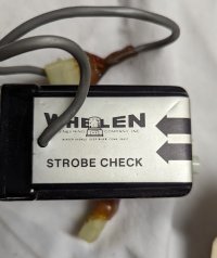
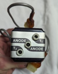
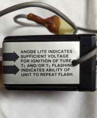
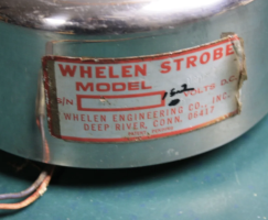
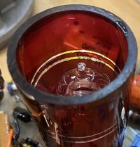
I have high voltage power but no ground at the light socket. I am investigating the diode between the main ground and the socket ground. I will also mess with the triggers as your suggested.
You are using an out of date browser. It may not display this or other websites correctly.
You should upgrade or use an alternative browser.
You should upgrade or use an alternative browser.
Old Whelen Power Supplies
- Thread starter JohnMarcson
- Start date
I have high voltage power but no ground at the light socket. I am investigating the diode between the main ground and the socket ground. I will also mess with the triggers as your suggested.
So the plot thickens... I can fire it once for every time I ground the trigger cap. It only fires once. I am sure I have a ground problem somewhere with the timing or triggering. I am checking all grounds. Here is a video.
And you replaced that big fat diode between the tube ground and gound-ground?So the plot thickens... I can fire it once for every time I ground the trigger cap. It only fires once. I am sure I have a ground problem somewhere with the timing or triggering. I am checking all grounds. Here is a video.
And you replaced that big fat diode between the tube ground and gound-ground?
Yes, that didn't seem to help.
You're doing pretty much what the SCR is supposed to do (by grounding the trigger cap via the purple wire).
This is where I use a simple Arduino to check if the SCR is working:
https://youtu.be/iuXxFLVTljY
As you can (hopefully) see, I yanked out the AEI-219 and inserted a control signal coming from the arduino (also making them share GND).
So earlier, I thought I heard trigger pulses in your earlier vid. I _didn't_ hear them in the most recent one.
Your observation about a missing tube-ground (and analysis leading to the big fat diode) made perfect sense. I don't understand why things aren't working right now...(aaarrrggg...)
Last edited:
I think you might be mistaking me knocking into stuff for trigger in the first video. I don't think I have been getting trigger pulse at any point now that I think about it. When I shocked myslef it was a constant shock instead on in pattern like usually. I will install that new capacitor that likely doesn't matter when it gets here and keep looking for ground issues. Any ideas on how I can isolate or test for trigger?You're doing pretty much what the SCR is supposed to do (by grounding the trigger cap via the purple wire).
This is where I use a simple Arduino to check if the SCR is working:
https://youtu.be/iuXxFLVTljY
As you can (hopefully) see, I yanked out the AEI-219 and inserted a control signal coming from the arduino (also making them share GND).
So earlier, I thought I heard trigger pulses in your earlier vid. I _didn't_ hear them in the most recent one.
Your observation about a missing tube-ground (and analysis leading to the big fat diode) made perfect sense. I don't understand why things aren't working right now...(aaarrrggg...)
Unfortunately I pulled the chip and it behaves the same way. I wonder if the chip is bad.
Last edited:
So you tried the other ports? (Looks like you did...looks like you soldered the white trigger wire onto the PCB).I think you might be mistaking me knocking into stuff for trigger in the first video. I don't think I have been getting trigger pulse at any point now that I think about it. When I shocked myslef it was a constant shock instead on in pattern like usually. I will install that new capacitor that likely doesn't matter when it gets here and keep looking for ground issues. Any ideas on how I can isolate or test for trigger?
Unfortunately I pulled the chip and it behaves the same way. I wonder if the chip is bad.
So maybe the AEI-219 isn't doing its job.
Make sure its getting fed - I measured ~+10V across here on mine:
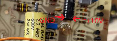
Here's a simple circuit showing the AEI-219 in isolation:
You very likely have other boards with AEI-219s in them. You could try to swap.
NOTE: The AEI-219 has must be oriented correctly. There's a small indentation and dimple to indicate "PIN#1" -- which is the "~10V" pin in the pic.
I tried the other outputs. I will check for power to the AEI then I am to the point of swapping the chip. I'm sure I have one somewhere, I'd rather have this odd 24v on working. I will swap one in and see. I think that's about where I'm at
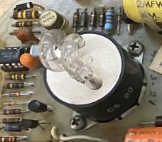
I just got a new chip courtesy of @RS485 . I replaced it and it is now working, video below. Thanks!
So it got new main capacitors, new "smoothing capacitor", new bulb, new diode to ground and a broken ground repaired. The strobe would fire manually by shorting the trigger after everything except the chip. Once the new AE-219 was installed it fired right up and I was able to "tune" the rate and cut off.
Video is super slow motion to capture everything. It sounds normal, the noise is distorted by the speed.
That reminds me...Are you sure you guys just won't get into doing some repairs to power supplies for those of us that still have working strobes since we'll never be able to find new strobe tubes..
I have an original "SA" ca. 1969 that was DOA.
The problem turned out to be a failed original flash tube so I needed to recreate it:
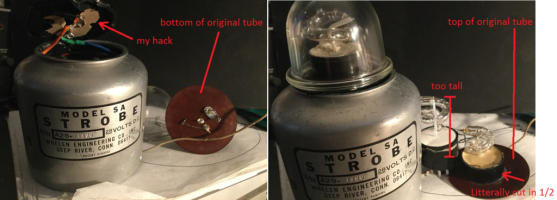
The original tube was unusually stout compared to all other flash tubes I had...so I chose to grab Tomar 4001 as it seemed to be sufficiently stout:
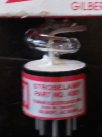
I cut the tube's socket down with a Dremel, removed all the material (plaster?), mounted it in an old cardboard Mogal-Base street-light socket insulator (rigid, inslutating, and nearly the size of the original), repacked it with tile grout and viola! It works:
That reminds me...
I have an original "SA" ca. 1969 that was DOA.
The problem turned out to be a failed original flash tube so I needed to recreate it:
View attachment 241321
The original tube was unusually stout compared to all other flash tubes I had...so I chose to grab Tomar 4001 as it seemed to be sufficiently stout:
View attachment 241322
I cut the tube's socket down with a Dremel, removed all the material (plaster?), mounted it in an old cardboard Mogal-Base street-light socket insulator (rigid, inslutating, and nearly the size of the original), repacked it with tile grout and viola! It works:
That is brilliant. FYI use respiratory protection when doing anything with "electrical grout dust", some of the older bulb bases supposedly had asbestos (maybe not as new as that tomar). This is a really good solution to bring life back to what is likely one of the first strobes. There is no reason a strobe supply should die with its bulb!
Thanks for the safety/health tip! (I'm pretty sure the Tomar tube was packed with plaster but that's damned good advice!)
Well that may have reminded you but you guys still didn't answer the question I mean that would be a hell of a thing if you guys could do that I don't have the capability to check that and I've already sent my stuff in to Whelen and gotten it back in worse condition than what I sent it in.That reminds me...
I have an original "SA" ca. 1969 that was DOA.
The problem turned out to be a failed original flash tube so I needed to recreate it:
View attachment 241321
The original tube was unusually stout compared to all other flash tubes I had...so I chose to grab Tomar 4001 as it seemed to be sufficiently stout:
View attachment 241322
I cut the tube's socket down with a Dremel, removed all the material (plaster?), mounted it in an old cardboard Mogal-Base street-light socket insulator (rigid, inslutating, and nearly the size of the original), repacked it with tile grout and viola! It works:
What exactly do you have that you'd like to get working?Well that may have reminded you but you guys still didn't answer the question I mean that would be a hell of a thing if you guys could do that I don't have the capability to check that and I've already sent my stuff in to Whelen and gotten it back in worse condition than what I sent it in.
Can you say more about how it was returned from Whelen, in worse condition than when you sent it?
Personally, this is fun stuff and if it becomes something else, I don't want any part of it.
I sent in the dash miser that was having a little bit of issues with its strobing and when I got it back they had cracked the housing and stripped out screws and say oh we couldn't find a problem with it It worked fine yeah right that's why I can see gunk where the chip was or the thermostat I can't remember what the heck it was and it still didn't work like useless....
Here's the guts of a dashmiser I have (ca. ~99):
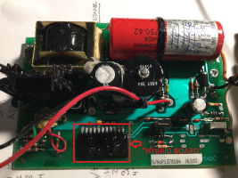
The problem with trying to repair these is the dreaded "HYBRID BOARD".
This was a custom made board that housed a fair amount of control electronics responsible for:
- Flash pattern control timing
- Current and over voltage sensing
- Supervisory inverter control
As you can see, its a sealed unit and not very revealing of how it works.
I have no idea if the problem with your device is rooted in the hybrid board but it would be pretty frustrating to chase some kind of subtle/sporadic/not-quite-right problem where a hybrid board is involved.
It might be fun to try to do it...and it could turnout that the hybrid board is the victim, not the cause (i.e. maybe it isn't always getting supply voltage...unlikely though). But it could take a lot of time and in the end, still turn out to be practically speaking, "unrepairable" as the only way to get a hybrid board is to harvest one from a similar/compatible unit.
To add insult to injury, the part number is printed on the underside of the hybrid board so prying it away from the PCB to identify it risks breaking it.
That said, it is _possible_ to try to repair it...but I don't think the dashmiser is unique/rare enough (yet) to justify such an effort.
When these fail I consider them toast except maybe after looking for the obvious. I repaired on of these by total luck. The capacitor connection was bad not at the board, but on the capacitor. It was like the lead separated from the cap. I made a tiny indentation in the metal disc at the bottom on the cap, roughed up the lead and made a solder mess. Much to my surprise it worked. Aside from that single experience, I have always considered dashmisers that fail to have "turned themselves into a remote version". Or you can play the game "what else can I fit in this housing".Here's the guts of a dashmiser I have (ca. ~99):
View attachment 242059
The problem with trying to repair these is the dreaded "HYBRID BOARD".
This was a custom made board that housed a fair amount of control electronics responsible for:
- Flash pattern control timing
- Current and over voltage sensing
- Supervisory inverter control
As you can see, its a sealed unit and not very revealing of how it works.
I have no idea if the problem with your device is rooted in the hybrid board but it would be pretty frustrating to chase some kind of subtle/sporadic/not-quite-right problem where a hybrid board is involved.
It might be fun to try to do it...and it could turnout that the hybrid board is the victim, not the cause (i.e. maybe it isn't always getting supply voltage...unlikely though). But it could take a lot of time and in the end, still turn out to be practically speaking, "unrepairable" as the only way to get a hybrid board is to harvest one from a similar/compatible unit.
To add insult to injury, the part number is printed on the underside of the hybrid board so prying it away from the PCB to identify it risks breaking it.
That said, it is _possible_ to try to repair it...but I don't think the dashmiser is unique/rare enough (yet) to justify such an effort.
Last edited:
That reminds me...
I have an original "SA" ca. 1969 that was DOA.
The problem turned out to be a failed original flash tube so I needed to recreate it:
View attachment 241321
The original tube was unusually stout compared to all other flash tubes I had...so I chose to grab Tomar 4001 as it seemed to be sufficiently stout:
View attachment 241322
I cut the tube's socket down with a Dremel, removed all the material (plaster?), mounted it in an old cardboard Mogal-Base street-light socket insulator (rigid, inslutating, and nearly the size of the original), repacked it with tile grout and viola! It works:
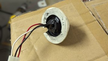
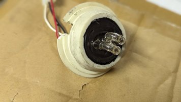
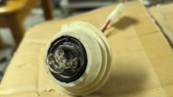
I had to replace an old aircraft bulb, here is my "less perfect" fix. I used a hide away strobe, an O ring and electrical insulation liquid/caulk

I don't think we dug into it. Unfortunately, the sample I have is from ~72, dipped in a heavy coat of wax, and I don't have anything else (labeled at 12V) to compare to. It came with the cruise light (burned out) and IIRC, it was the typical 12V bulb.I went back through the thread and didn't find the answer, but it's gotten pretty long and multi-topic here.....
Did we ever decide why older "pre-patent" Whelen strobes have 12 VDC crossed out and 15.2 written in? Is that the actual voltage they were tested at to maintain their flash rate?
View attachment 242751
I will look through my "written in 15.2" ones and see if there is any difference when run at 15.2 vdc. I have a few 1200s / senior strobes of various ages, one with the 15.2 designation. I will look for differences. Later Whelen stuff allowed a big range of voltages, sometimes 12-36. I wonder if that is meant for a specific industry to show compliance.I don't think we dug into it. Unfortunately, the sample I have is from ~72, dipped in a heavy coat of wax, and I don't have anything else (labeled at 12V) to compare to. It came with the cruise light (burned out) and IIRC, it was the typical 12V bulb.
I will look through my "written in 15.2" ones and see if there is any difference when run at 15.2 vdc. I have a few 1200s / senior strobes of various ages, one with the 15.2 designation. I will look for differences. Later Whelen stuff allowed a big range of voltages, sometimes 12-36. I wonder if that is meant for a specific industry to show compliance.
I think I can shed a little light on the subject... back in the '70s after most manufacturers had switched from generators to alternators and police cars and other smaller public safety vehicles were seeing a dramatic increase in electrical loads due to radios sirens and more lights, etc., the carmakers had to crank up the output from the alternators. They needed to have a steady supply of 13.5-ish volts under load at idle which wasn't too difficult to achieve, but one side affect was that the alternator output ramped up with both engine RPM and temperature. Those old Detroit-born V8s weren't known for being high winders, and combined with short rear ends, the motors were turning 4000-4500 RPM, but the alternators were putting out 15.2 volts. Of course your headlights were brighter, but they didn't last as long, and battery life was severely shortened as well. I can see that potentially wreaking havoc on your new, very expensive, state-of-the-art strobe beacon that was initially made for 12 volts... Whelen likely made the necessary changes, and then later solving multiple problems by engineering systems that worked on both 12v and 24v systems (and ostensibly both 14v and 28v aircraft systems, though the FAA probably took a dim view of that, so to speak, but that's a different discussion entirely).
I think I can shed a little light on the subject... back in the '70s after most manufacturers had switched from generators to alternators and police cars and other smaller public safety vehicles were seeing a dramatic increase in electrical loads due to radios sirens and more lights, etc., the carmakers had to crank up the output from the alternators. They needed to have a steady supply of 13.5-ish volts under load at idle which wasn't too difficult to achieve, but one side affect was that the alternator output ramped up with both engine RPM and temperature. Those old Detroit-born V8s weren't known for being high winders, and combined with short rear ends, the motors were turning 4000-4500 RPM, but the alternators were putting out 15.2 volts. Of course your headlights were brighter, but they didn't last as long, and battery life was severely shortened as well. I can see that potentially wreaking havoc on your new, very expensive, state-of-the-art strobe beacon that was initially made for 12 volts... Whelen likely made the necessary changes, and then later solving multiple problems by engineering systems that worked on both 12v and 24v systems (and ostensibly both 14v and 28v aircraft systems, though the FAA probably took a dim view of that, so to speak, but that's a different discussion entirely).
I think this is a pretty logical hypothesis. They probably wanted to avoid a bunch of calls asking about the safe top voltage or print all new literature (that people discard anyway). Why bother with that when you can just sharpie the top voltage on the product? Good points...
Got a hold of a pair of these NIB, 36V, model "2200" PSs.
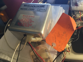
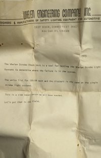
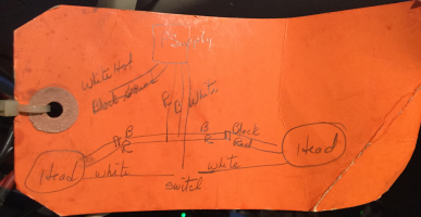
including a factory, hand-written tag as to how it supposed to be wired:
I drilled out the rivets on one of them to reveal the power transistors date of "7326" which I take to mean 26th weak of 1973.
I don't have 36V to feed it but 28v gets her to flash exactly as I'd hoped...SF around 72 FPM when fed with ~27V.
Based on the hand-written diagram, I gather when installed in the intended application, user would choose via switch, which of two heads would flash.
I think its safe to say this is non-aircraft (Whelen already had very specific part numbers for aircraft applications by '73) -- Given the 36V input (and the main transformer is labeled, "TD36") I'm guessing this was industry specific, but I have no idea which one...mining? railroad? forklifts? -- no idea).
In any case, I think this is a cool PS and I'm dying to tinker with it some more..but I don't think it will make for terribly interesting videos as its plain old SF from ~1973.

including a factory, hand-written tag as to how it supposed to be wired:

I drilled out the rivets on one of them to reveal the power transistors date of "7326" which I take to mean 26th weak of 1973.
I don't have 36V to feed it but 28v gets her to flash exactly as I'd hoped...SF around 72 FPM when fed with ~27V.
Based on the hand-written diagram, I gather when installed in the intended application, user would choose via switch, which of two heads would flash.
I think its safe to say this is non-aircraft (Whelen already had very specific part numbers for aircraft applications by '73) -- Given the 36V input (and the main transformer is labeled, "TD36") I'm guessing this was industry specific, but I have no idea which one...mining? railroad? forklifts? -- no idea).
In any case, I think this is a cool PS and I'm dying to tinker with it some more..but I don't think it will make for terribly interesting videos as its plain old SF from ~1973.
That is interesting in all the ways you highlighted.Got a hold of a pair of these NIB, 36V, model "2200" PSs.
View attachment 244008
including a factory, hand-written tag as to how it supposed to be wired:
View attachment 244009
I drilled out the rivets on one of them to reveal the power transistors date of "7326" which I take to mean 26th weak of 1973.
I don't have 36V to feed it but 28v gets her to flash exactly as I'd hoped...SF around 72 FPM when fed with ~27V.
Based on the hand-written diagram, I gather when installed in the intended application, user would choose via switch, which of two heads would flash.
I think its safe to say this is non-aircraft (Whelen already had very specific part numbers for aircraft applications by '73) -- Given the 36V input (and the main transformer is labeled, "TD36") I'm guessing this was industry specific, but I have no idea which one...mining? railroad? forklifts? -- no idea).
In any case, I think this is a cool PS and I'm dying to tinker with it some more..but I don't think it will make for terribly interesting videos as its plain old SF from ~1973.
The 2200 was listed as a "single head" remote power supply for one remote strobe with the dimensions of the 5.5" diameter and 6" high, (essentially a 800 dome or "F" head) with choice of flat or pipe mount. They stated you could use other equivalent heads, but the 2200 defaulted to the noted size. The first catalog shot is the earlier one you have, the later page is the subsequent Strobe II version, but the idea is the same, different model numbers assigned by the strobe head being used with the supply.
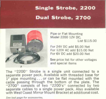
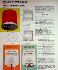
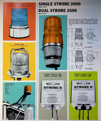
So they were using the single head supply to run two heads, one head at a time, which may be the reason for the hand drawn diagram on the factory tag. This technically isn't how the 2200 was meant to be used.
Like you mentioned, forklifts, tugs for various industries, people movers, jobsite rail cars, and various industrial cars/carts use 36 vdc. The swapping between two heads makes me think it is for industry specific rail and/or mining. The leading, or more likely trailing, end (front would have a head lamp) could be set to flash as a direction of travel indicator. This also could be as simple as a people mover at a large factory or airport, those are 36 volts often times. The toggling is what makes me lean towards a specific industry. Their actual full-size railroad line of the "2000" series had the letter R after the number and heat fins. They were 75vdc.
Cool find, especially the hand drawn diagram on the tag; thanks for posting it.
We ruled out aircraft for the 36vdc system above, and I think we can rule out full size rail too. That line was specific and separate.
More on the railway side of things;
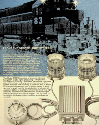
Whelen's 2700RR was the version of the 2X00 series of remote strobes meant for trains. Two things of note here. The first is the supply itself has heat fins and special connections for railway use. The second is that a more common place for the dual system was as ditch lights or lower down on the "fenders" at the front. That was two sealed beams, PAR56 I believe. The catalog doesn't mention those, instead the sealed beam 2800RR package is for the rear of the train and simultaneous flashing. The "very high intensity red" system mentioned used a huge bulb, I actually have one and they were different than the standard sealed beams. No fluting and clear glass with a colored filter inside.
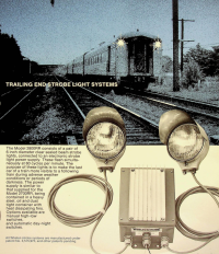
Again, special connectors and heat fins. Most of this stuff was 75vdc, but Whelen would do strobes in any voltage you paid for. My 75vdc 5200 was from the front of a switching yard engine.
All in all, railroad stuff was interesting, but not anything like the 36vdc stuff just posted above and carried the "RR" suffix and special connectors.
More on the railway side of things;

Whelen's 2700RR was the version of the 2X00 series of remote strobes meant for trains. Two things of note here. The first is the supply itself has heat fins and special connections for railway use. The second is that a more common place for the dual system was as ditch lights or lower down on the "fenders" at the front. That was two sealed beams, PAR56 I believe. The catalog doesn't mention those, instead the sealed beam 2800RR package is for the rear of the train and simultaneous flashing. The "very high intensity red" system mentioned used a huge bulb, I actually have one and they were different than the standard sealed beams. No fluting and clear glass with a colored filter inside.

Again, special connectors and heat fins. Most of this stuff was 75vdc, but Whelen would do strobes in any voltage you paid for. My 75vdc 5200 was from the front of a switching yard engine.
All in all, railroad stuff was interesting, but not anything like the 36vdc stuff just posted above and carried the "RR" suffix and special connectors.
UPDATE: I got around to opening the 2nd unit I received and learned it was repaired under warranty. It contained this nice little artifact:
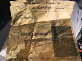
I found a web site for what I *think* might be the recipient: www.airtek-inc.com
They specialize in air compressors and hydraulics.
So the 2200 could have been for their own internal use, or for something they made for a customer of theirs.
Thanks for all those details and pics regarding RR systems, John! -- I didn't even know the "RR" products existed!
That's cool. I love the old internal Whelen documents.UPDATE: I got around to opening the 2nd unit I received and learned it was repaired under warranty. It contained this nice little artifact:
View attachment 244017
I found a web site for what I *think* might be the recipient: www.airtek-inc.com
They specialize in air compressors and hydraulics.
So the 2200 could have been for their own internal use, or for something they made for a customer of theirs.
Thanks for all those details and pics regarding RR systems, John! -- I didn't even know the "RR" products existed!
Some compressors and pumps run on 36vdc... so like you said; could be something they build for customers. I would think if it were one of their products the end user would be sending it in, not them. It's probably for something they used in-house like a forklift, conveyor system, gantry crane etc. So many factory type items run on 36vdc it's hard to say. It could be a loading dock light or a gate light. The toggle is the only real clue, that they were running two beacons and swapping between them. I think that makes it sound like an in house indicator for something; stop or go, forward or reverse, open or closed, up or down, etc.
No matter what it is a cool slice of Whelen history and the date was close too.
@JohnMarcson , I just finished watching your excellent and comprehensive history on Whelen’s Commander beacon posted on YouTube and I have a question about the directional reference (Front). On my blue DMS, the label is prominent as you can see, but the fresnel fluting does not appear to be different from any angle. I always assumed it had to do with the profile of the strobe tube. Because my tubes are the vertical loop style (as opposed to the horizontal loop in your video), I turned the “doughnut hole” toward the front (In photo L to R). Or would it be more effective from the side. Or does it really make any difference. Any insight?@dmathieu, ask and you shall receive.
As you can hear, it’s a double flash but the video is too slow to capture:
RedBlue
BTW, I will start exercising my capacitors more frequently now. Thanks for the tip.
Attachments
I don't see the pic you are referring to, but I would look to see if there is an arrow impression in the dome too. It is possible that after they stopped offering the domes with the fluting favoring the front they continued to have a preference on orientation. I'm not sure exactly how labeling the dome would make sure the strobe tube oriented correctly unless your label is on the actual base or board. Maybe I'm not looking at the right picture or the wrong one got uploaded but I'd be curious to see what you have. I wouldn't be surprised if there were some variations in domes, especially around the year when they stopped making the front specific type. When they switched to the loop style tubes is around the time when the domes became omnidirectional, so I don't think the tube is a huge factor but, again, I'm not 100% sure. I have an Austin model 2020 that I think the orientation of the tube matters, but I also could be imagining that.@JohnMarcson , I just finished watching your excellent and comprehensive history on Whelen’s Commander beacon posted on YouTube and I have a question about the directional reference (Front). On my blue DMS, the label is prominent as you can see, but the fresnel fluting does not appear to be different from any angle. I always assumed it had to do with the profile of the strobe tube. Because my tubes are the vertical loop style (as opposed to the horizontal loop in your video), I turned the “doughnut hole” toward the front (In photo L to R). Or would it be more effective from the side. Or does it really make any difference. Any insight?
View attachment 247322
BTW, I will start exercising my capacitors more frequently now. Thanks for the tip.
This is what should be under the sticker
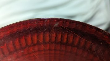
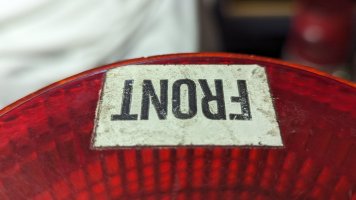
These two beacons have omni-directional domes, but I can see why the orientation of the bulb could potentially matter.
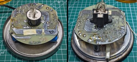
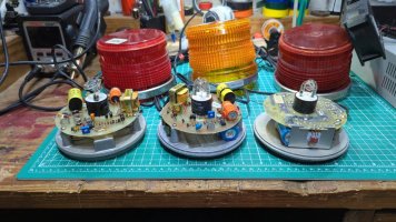
This (below) is how I orient the bases of mine. I'm not sure that it's accurate because the way the cords come out lead me to believe this might not have been the intention. From left to right the dates are 1980, 1983, 1984. There was a large change in circuit board style from 83 to 84. In fact, the whole beacon reverted to the Austin electronics design, including the base. On all 3 of these I do have a front specific dome, however, on the Austin version of this beacon, I do not (1985).
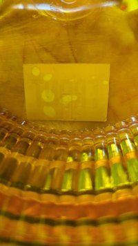
Finally, this is what the labeled domes look like from underneath on mine... There is both the paper label and the dome does have the imprint if it can be made out in this picture.
Last edited:
I remember Whelen advertising that the dome was optically corrected, and the arrow to the front gave the best beam/spread to the front, in the direction of the arrow. There was nothing said about how the dome was oriented on the light itself. It was all dome from what I remember.
That's correct, but I think he's saying his dome has the marking label but the dome isn't designed this way. I think he is asking if the later ones with omni-directional domes still have a "font" based on bulb shape.I remember Whelen advertising that the dome was optically corrected, and the arrow to the front gave the best beam/spread to the front, in the direction of the arrow. There was nothing said about how the dome was oriented on the light itself. It was all dome from what I remember.
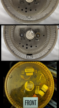
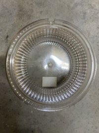
It is pretty hard to notice, but the fluting is shaped to make the light concentrate to the front. The "senior" strobes, DMS, and internal 5000/6000 optics were all this way. The DMS is a cut down "senior" strobe. The 5000 and 6000 took the "senior" dome and cut a hole in the top and used it as an internal filter. They all have this imprinted arrow on the dome, but some also have a sticker on the dome over the imprint and some may have a sticker on the base too.
The shape of the fluting "aimed front" (5000 and DMS)
The video he is talking about
The spot where it is explained
@RS485 put an incandescent lamp on the inside of one and we were able to see a slight difference, I can't find the pics/thread.
Last edited:
That pic of light cast from an incandescent lamp in the "optically corrected" clear lens is at the bottom of this post:That's correct, but I think he's saying his dome has the marking label but the dome isn't designed this way. I think he is asking if the later ones with omni-directional domes still have a "font" based on bulb shape.
It is pretty hard to notice, but the fluting is shaped to make the light concentrate to the front. The "senior" strobes, DMS, and internal 5000/6000 optics were all this way. The DMS is a cut down "senior" strobe. The 5000 and 6000 took the "senior" dome and cut a hole in the top and used it as an internal filter. They all have this imprinted arrow on the dome, but some also have a sticker on the dome over the imprint and some may have a sticker on the base too.
The shape of the fluting "aimed front" (5000 and DMS)
View attachment 247335
The video he is talking about
The spot where it is explained
@RS485 put an incandescent lamp on the inside of one and we were able to see a slight difference, I can't find the pics/thread.
Gen 1 Whelen Commander Glass Internal Optics, possible Origin Story
Another story of something taken from the aviation industry near the birth of automotive strobes is likely the glass internal optics of the first generation Commander beacon. This runway light optic is exactly the same minus the open top, which looks to have been ground off in the commander...
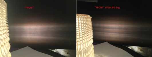
If you stand about 20 feet away at the horizontal angle when it's flashing, you can see the diff between facing the "FRONT>" directly compared to 90 degrees off to the side. The flash is definitely spread out over the width of the lens where as at the 90 degree angle, it appears narrow.
That's what I was looking for. I knew I had the pics of the actual fluting highlighted, but I couldn't find that test you did. Thanks.That pic of light cast from an incandescent lamp in the "optically corrected" clear lens is at the bottom of this post:
Gen 1 Whelen Commander Glass Internal Optics, possible Origin Story
Another story of something taken from the aviation industry near the birth of automotive strobes is likely the glass internal optics of the first generation Commander beacon. This runway light optic is exactly the same minus the open top, which looks to have been ground off in the commander...elightbars.org
If you stand about 20 feet away at the horizontal angle when it's flashing, you can see the diff between facing the "FRONT>" directly compared to 90 degrees off to the side. The flash is definitely spread out over the width of the lens where as at the 90 degree angle, it appears narrow.
Image courtesy of @RS485
Wow!! Amazing! I never would have noticed the subtle variations in the fluting without your drawing on the photo! So, on DMS domes, it’s easy to determine “Front”…it’s opposite of the notch for the power cord. I checked my other two domes (without labels) and they’re the same. Now, @RS485, will the orientation of the flash tube make a difference? Based on the power cord on the DMS, it appears to favor the “doughnut hole” facing front.
P.S. Thanks for the amazing depth of knowledge shared here @RS485 & @JohnMarcson !

P.S. Thanks for the amazing depth of knowledge shared here @RS485 & @JohnMarcson !
Last edited:
That's an intriguing questions but I'm sorry to say I don't know the answer.Wow!! Amazing! I never would have noticed the subtle variations in the fluting without your drawing on the photo! So, on DMS domes, it’s easy to determine “Front”…it’s opposite of the notch for the power cord. I checked my other two domes (without labels) and they’re the same. Now, @RS485, will the orientation of the flash tube make a difference? Based on the power cord on the DMS, it appears to favor the “doughnut hole” facing front.
View attachment 247351
P.S. Thanks for the amazing depth of knowledge shared here @RS485 & @JohnMarcson !
We know lenses for incandescent/halogen light sources are designed around a pretty tight focal point. Strobe flashtubes don't have a single focal point and there are a few different flashtube shapes in play here so I'd think they're always somewhat out of focus. I'm sure there's some difference (there has to be -- the tubes have non-uniform shapes and no single focal point), but I can't assert any particular tube orientation makes a visible difference.
My $0.00002
I would agree that strobes being more diffuse of design by their nature is going to lessen the impact. I can't tell a difference myself viewing a sample of the units I have. I will say that Whelen made several optics and bulb shape changes and seemed to care about the height and position of the tube when designing strobe lenses/domes in general. The height and viewing angle (vertical factors) seem to matter more than the horizontal viewing angle going around 360 when I looked. That said, the "simple U" tubes are significantly more narrow in profile from their "sides" than head on, but in a "blind" test I couldn't tell which side I was viewing. I guess my answer is; logically it should matter, but I cannot perceive it, subjectively tell a difference, nor can I objectively measure it.That's an intriguing questions but I'm sorry to say I don't know the answer.
We know lenses for incandescent/halogen light sources are designed around a pretty tight focal point. Strobe flashtubes don't have a single focal point and there are a few different flashtube shapes in play here so I'd think they're always somewhat out of focus. I'm sure there's some difference (there has to be -- the tubes have non-uniform shapes and no single focal point), but I can't assert any particular tube orientation makes a visible difference.
My $0.00002
The early DMS seems to have a bigger problem with the internal electronic components casting dark spots than bulb orientation and that might be a reason to consider "dome on base" orientation.

