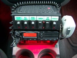
"Tiering" Lighting on a vehicle

Mr911

Member
Member
Jun 2, 2010
339
1
56
Northeastern Pennsylvania
Ok...I have a question for the wiring gurus on the board here. Let's say we have a vehicle with 9 individual LED light heads on a single "ON/OFF" switch...If I were to use an "ON/OFF/ON" switch would it be possible to activate only 5 heads in one "ON" direction and all 9 in the other "ON" direction.


Other questions would be; would any other items be needed (i.e. Diodes, etc)?


The reason I am asking is I would like to do this with my current lighting setup and have no room in my current switchbox to simply split the lights into two switches. Any help, feedback, suggestions would be welcome.


Thanks everyone!
 
Whether you can put 9 LED lights on one circuit and 5 on another will depend upon:


1. The current draw (amperage) of each lighthead


2. The amperage rating of the switch; and


3. the length and diameter (gauge) of the wiring.


If all the nine lightheads are LIN3 or TIR3 on a passenger car or pickup, and


you have a thirty (30) amp capacity switch, it might be possible.


If the lights are much larger (more LED diodes), then you might need relays and a more complicated wiring scheme.
 
tnems7 said:
Whether you can put 9 LED lights on one circuit and 5 on another will depend upon:
1. The current draw (amperage) of each lighthead


2. The amperage rating of the switch; and


3. the length and diameter (gauge) of the wiring.


If all the nine lightheads are LIN3 or TIR3 on a passenger car or pickup, and


you have a thirty (30) amp capacity switch, it might be possible.


If the lights are much larger (more LED diodes), then you might need relays and a more complicated wiring scheme.

I understand what you are saying and have already calculated everything you have mentioned. I already have all 9 light heads on one switch and it has been functioning well for quite some time now. What I am getting at is the question of is it possible to keep all nine on the switch in the first "ON" position and in the other "ON" position have only 5 heads activated? (Similar to a "response mode" - all heads on vs. a "warn mode" - limited heads on)
 
unless you can find a switch that has one output on in the first "ON" position and both outputs on in the second "ON" position, you are going to need diodes to stop back-feed from the primary to the secondary lights.
 
JraCrir said:
unless you can find a switch that has one output on in the first "ON" position and both outputs on in the second "ON" position, you are going to need diodes to stop back-feed from the primary to the secondary lights.

Wouldn't a simple DPDT (Center Off) switch do the job?
 
Zack said:
Wouldn't a simple DPDT (Center Off) switch do the job?

Not with what Mr911 wants to do. He wants 5 of the LEDs powered on both poles, and 4 others only powered on one. This means 5 of the LEDs are wired to both poles. When switched to only power those 5, the power can back-feed down the line to the second pole and power the other four lights.


Basic picture showing how I would wire the power for the leds from the switch (does not show switch power or any grounding)


[Broken External Image]:http://i1229.photobucket.com/albums/ee479/JraCrir/Untitled.png
 
JraCrir, I don't think you understand what a DPDT switch is. There are two poles for each of two throws.


[Broken External Image]:http://pictures.xbox-scene.com/2/endisable/03.jpg


Terminal 2 is common to terminals 1 and 3.


Terminal 5 is common to terminals 4 and 6.


Connect terminals 2 and 5 to your power source.


Connect terminal 1 to your group of four LEDs.


Connect terminals 3 and 6 to your group of five LEDs.


Leave terminal 4 unused.


Throwing the switch in one direction will be Warning Mode, throwing the switch another direction will be Response Mode.
 
shues said:
JraCrir, I don't think you understand what a DPDT switch is. There are two poles for each of two throws.

[Broken External Image]:http://pictures.xbox-scene.com/2/endisable/03.jpg


Terminal 2 is common to terminals 1 and 3.


Terminal 5 is common to terminals 4 and 6.


Connect terminals 2 and 5 to your power source.


Connect terminal 1 to your group of four LEDs.


Connect terminals 3 and 6 to your group of five LEDs.


Leave terminal 4 unused.


Throwing the switch in one direction will be Warning Mode, throwing the switch another direction will be Response Mode.

Agreed. Use a DPDT switch. That would be your best bet.


BJ
 
Jeff & BJ,


that would indeed be the easiest. However, finding a DPDT switch that will fit in the space alotted (switch is currently second from the left). I can modify the panel to accept a DPDT if necessary...that's not a big issue. I'm just wondering if JraCir's would be more feasable given the current layout in the photo below. (Either that or totally replace the current switch panel - of which I am not a big fan of doing at this point)


ai159.photobucket.com_albums_t151_chief60mac_Explorer_20Pics_CONSOLE3.jpg
 
Wouldn't it just be a lot easier to have 2 switches?


In my Jeep I used 3 switches to get the same effect as a 3-position slider without the big box.


1 is rear, 2 is grille and front HAW, and 3 is dash. (I also have a 4th with a different color light as an extra, like for my Christmas wreath or something like that)


Anyway, couldn't you just do something like that with the first 3 switches? Make one like a low-priority rear flash, one the rest of the back and some of the front, and the third everything else?
 
Last edited by a moderator:
rys.nvf4-1.jpg


You could use a DPST relay. These are the 5 terminal relays the look like 30-40a auto relays.


85 or 86 -ground


86 or 85 -trigger


30-lights


87A - switch 1


87 - switch 2


#1 and #2 are light groups. switch #1 thru the relay (87A) to the #1 lights (30). switch #2 would power #2 lights and power would also go to 87 and 86 or 85 to re-trigger #1 lights (30).


When I say switch #1 and #2, obviously it could also be an on/off/on switch of sufficient capacity.
 
I've never seen a DPDT switch that will fit the "standard" switch opening like what you have in our switch box... It looks like rwo978s suggestion would lead to the least amount of modification...
 
JraCrir gave you the diagram for a SPDT. Combine a SPDT with rwo's suggestion of a relay and you are good to go. As long as you can find a switch to match the original.
 
I would agree with the relay, wire your 5 leds to the relay, wire pole 87a to the other 4 leds then to the top of a on off on, then 87 to the bottom of the switch and call it done. No need to modify or replace the switch panel.


Just my 2¢
 
Thanks everyone for the great feedback...although all are great suggestions, I have decided to go with Ryan's suggestion of using the DPDT relay and I already have another ON/OFF/ON switch for that box. Seems like that will work the best for this application, again thank you for all the suggestions...this is what makes this board great!
 
Mr911 said:
Thanks everyone for the great feedback...although all are great suggestions, I have decided to go with Ryan's suggestion of using the DPDT relay

A DPDT relay isn't going to work. This relay has a pair of contacts that are closed and a set that are open when no power is applied to the relay. Applying power to the relay energizes the coil, closing the previous open contacts and opening the previous closed contacts. Whether power is being applied to the relay, or not, one pair of contacts will always allow power though the relay. All the off/on/off switch controls is whether the coil that moves the contacts from one of the above two modes to the other one. Even with the switch in the off position, power will flow through the normally closed contacts to the lights hooked up to that side of the relay. If your going to use relays with that switch, you need two either single pole/single throw (spst) or the more common double throw/single throw (spdt) and just use the normally open side of each relay.
 
I mentioned DPST in my reply. Probably just got it mixed up when he posted DPDT above.
 
rwo978 said:
I mentioned DPST in my reply. Probably just got it mixed up when he posted DPDT above.

That won't work either. Look at this illustration:


200px-Relay_symbols.svg.png


Your DPST relay only has power to contacts when the coil is energized. Otherwise it is the same as having a switch in the off position. The only difference between a DPST and a DPDT relay is that the DPST has no closed contacts when no power is applied to the coil while a DPDT relay ALWAYS has power applied to either the normally closed or normally open contacts depending on whether the coil is energized or not.
 
well, whatever it's called, the one pictured is the right one.:oops: :razz:
 
rwo978 said:
well, whatever it's called, the one pictured is the right one.

Ryan,


After looking at a few stores, I have not had any luck in finding a match to your original picture. Would you be able to direct me as to where I might be able to get one?


Thanks,
 
Truck stops... seriously. That's where I've always found them. It's basically a Bosch 30-40 amp auto type relay with the extra center pin.
 
rwo978 said:
well, whatever it's called, the one pictured is the right one.:oops: :razz:

Then tell me how the right one takes care of the application? When no power is applied to the coil, power flows through B & C; when poer is applied to the coil, power flows through A & C. So even with the switch turned off, or even if the switch was not even hooked up to the relay, power will still flow through B & C.


If one of you gets any of these relays to work in the application with the switch discussed, I want to hear how you did it. Maybe someone makes a relay with dual coils that has two sets of normally open contacts, then that would most likely do the job correctly.
 
GaryErrol said:
Then tell me how the right one takes care of the application?

You'll need to reread what he wrote originally. I reread it, and then drew a diagram based on what he wrote. Using an SPDT relay, it looks like it should work flawlessly.


[Broken External Image]:http://img710.imageshack.us/img710/4070/83332740.png


This setup should function as follows:

  • LEDs 1 is the group of 5 LEDs.
  • LEDs 2 is the group of 4 LEDs.
  • Turning on SW1 turns on LEDs 1, or "warning mode".
  • Turning on SW2 turns on both LEDs 1 and LEDs 2, or "response mode".
 
Thanks Shues. You're diagram helped what I was trying to explain, but didn't have the time to draw out.


I used this very setup back when I had a rotator bar on my truck, so I know it worked. Used the same on/off/on switch. One way was the amber (2 inner) rotators and the other way was the amber and blue (2 outer and center) rotators. I also used a similar setup on another switch for amber flashers/leds and then the other way for amber and blue flashers/leds. It worked out great.
 
I still don't understand the need for a relay. You can do what your doing by simply using the on/off/on three way switch originally mentioned. From what I can see all of the power to each set of lights has to pass through each switch. Normally relays are used when you don't want large ampere's passing through the switch. But yes this will work although for the life of me, I can't understand why the relay is needed.
 
It probably comes down to this... how easy is it to find a diode of adequate amperage vs the relay? Cost difference? I can go to several places in town and find the relay. Diode, I'm thinking 1-2. And, I've never used diodes. I'm not familiar with them. Hence, why I suggested the relay.
 

Forum Statistics

Threads
54,612
Messages
452,479
Members
19,442
Latest member
Rileyjackson