Todays Swap Meet Find

Today found this mystery strobe light at the swap meet, had no clue who made it but couldnt pass up a 5 dollar light.

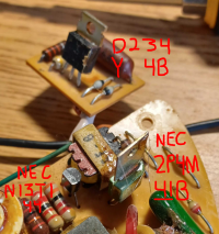
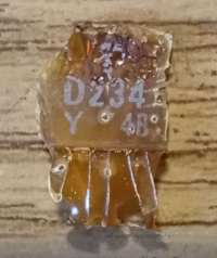
Once i got home and looking at the label really closely i could make out "Warn Industries" of Kent, Washington, and after applying 12v power to the leads nothing happened. I could see on my power supply it was consuming a few fractions of an amp but heard and saw nothing.

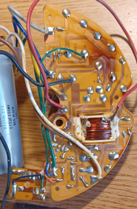
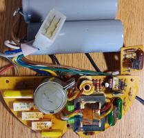
So looking for some advice, is there a way to test to see if the electronics are shot or just the bulb?

Either way if its non repairable its still a cool looking light that id restore cosmetically, maybe hope that ill be able to find a replacement dome too but thats probably a reach.
1764554527465.png1764554607901.png1764554628872.png
 
  • Like
Reactions: kitn1mcc
I gar-un-tee there are strobe nerds (all respect intended) on this site that can help you research and resurrect this light from obscurity. You’ve come to the right place.

P.S. looks like a Whelen strobe bulb…but what do I know (I have 3 DMSs).
 
First, just to be sure, is the unit labeled for 12VDC?
Next, I recommend taking the PCBs out and going over the solder points looking for a cold solder joint. This would be an easy fix.

According to:
the "2SD217" is an NPN transistor. It is the heart of the charging circuit.
Identify the "BASE" "EMITTER" and "COLLECTOR" pins and measure to verify you see:

~12VDC between "EMITTER" and "COLLECTOR"
~somewhere between ~1.5 to 5 VDC between "BASE" and "EMITTER" (sorry, I just don't remember exactly what it would be...but it must be below 7VDC according to the data sheet).

If you confirm these voltages, it suggests the transistor has failed and should be replaced.
If you don't see the expected voltages, then work backwards from there to identify the cause.

Also, could you please try to identify these parts (circled in red):
1764577041796.png
Knowing what they are might help hint at circuit's fundamental design.

Hope this helps!
 
First, just to be sure, is the unit labeled for 12VDC?
Next, I recommend taking the PCBs out and going over the solder points looking for a cold solder joint. This would be an easy fix.

According to:
the "2SD217" is an NPN transistor. It is the heart of the charging circuit.
Identify the "BASE" "EMITTER" and "COLLECTOR" pins and measure to verify you see:

~12VDC between "EMITTER" and "COLLECTOR"
~somewhere between ~1.5 to 5 VDC between "BASE" and "EMITTER" (sorry, I just don't remember exactly what it would be...but it must be below 7VDC according to the data sheet).

If you confirm these voltages, it suggests the transistor has failed and should be replaced.
If you don't see the expected voltages, then work backwards from there to identify the cause.

Also, could you please try to identify these parts (circled in red):
View attachment 256510
Knowing what they are might help hint at circuit's fundamental design.

Hope this helps!
There is a label on the bottom side of the light that i could just barely make out saying "For 12V" and nothing else, the label from age has gone completely clear and i could only make out some letters by shining the sun on it at a specific angle.

Also did manage to take out the electronics last night, look them over and give them a clean, as far as i saw all the solder joints looked right.

For the rest ill have to wait till i can mess with it again later today, and ill get back to you on what those components are.
 
  • Like
Reactions: RS485
First, just to be sure, is the unit labeled for 12VDC?
Next, I recommend taking the PCBs out and going over the solder points looking for a cold solder joint. This would be an easy fix.

According to:
the "2SD217" is an NPN transistor. It is the heart of the charging circuit.
Identify the "BASE" "EMITTER" and "COLLECTOR" pins and measure to verify you see:

~12VDC between "EMITTER" and "COLLECTOR"
~somewhere between ~1.5 to 5 VDC between "BASE" and "EMITTER" (sorry, I just don't remember exactly what it would be...but it must be below 7VDC according to the data sheet).

If you confirm these voltages, it suggests the transistor has failed and should be replaced.
If you don't see the expected voltages, then work backwards from there to identify the cause.

Also, could you please try to identify these parts (circled in red):
View attachment 256510
Knowing what they are might help hint at circuit's fundamental design.

Hope this helps!
So here are the rest of those transistors.

The printing on the D234 came off but only what i assume was the brand was unreadable.

Attached are some more pictures of the whole power supply to give a better idea of the whole thing, also to test that one transistor next to the strobe bulb i assume i would be testing it with power on to the power supply?
 

Attachments

  • 1764616059678.png
    1764616059678.png
    1.1 MB · Views: 11
  • 1764616278661.png
    1764616278661.png
    563.9 KB · Views: 12
  • 1764616373176.png
    1764616373176.png
    1.1 MB · Views: 11
  • 1764616415206.png
    1764616415206.png
    1.2 MB · Views: 11
  • Like
Reactions: kitn1mcc and RS485

Forum Statistics

Threads
56,102
Messages
457,943
Members
20,358
Latest member
LittleWingNut