Upgrading corners on an LFL Patriot - what am I missing?

WS295

Member
May 31, 2012
28
NE, USA
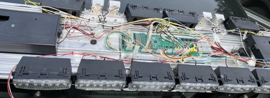
Recently installed a brand new clear 54” lens kit on my 2007 Patriot. I’ve already replaced the alleys and takedowns with LR11s, and so I just need to replace the strobe corners. I have a Whelen four-channel LED ballast (which I bought after mistakenly buying just a hollow plastic ballast and then a control board, but I think is what I need). When I bought the control board, it came with the output harnesses, but unfortunately the connector on the one for the corners now doesn’t match up with the eight-pin connector on my proper ballast.

What am I missing here? I found the Whelen PDF on how to upgrade from strobe to LED, so I know I take the corners out, take the top off, remove my alley lights, and slide out the driver’s side strobe supply and replace it with this ballast. But am I missing harnesses to connect the ballast to the main supply source and go out to the four corner LEDs?

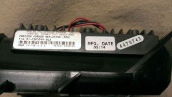
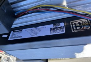
Ballast tech label:
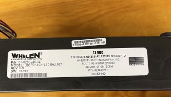
F99CDF9C-7AFB-4BA2-ADF0-52C1139682EC.jpeg

Connector from the harness I have is on the left, connector coming out of the ballast is on the right. Other connector coming out of it is roughly the same size, and I think a 6-pin:
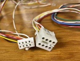
AF259891-5D06-44B9-9B0E-D8BA4CC35150.jpeg

The Whelen tech sheet mentions some kind of ballast interconnect harness, so I think that’s what I need here, but haven’t found much on it searching online. Please help, just want to buy whatever last few pieces I need and hopefully stop buying the wrong things.

Thanks
 

firebuff17

Member
Mar 28, 2011
776
CT
Can you get a pic of the control board that you describe?
It sounds like you have a control board for passive LED’s (newer technology) and according to your description and pic, you have a ballast driver for LED’s. Which if your set on using the ballast (it’s fine if you do), you need LED heads that run off the ballast, and a different control board. Not all LED’s can be run off the ballast.
Might be easier to get the proper LED’s to run off that control board, if it actually is a newer control board.
 

WS295

Member
May 31, 2012
28
NE, USA
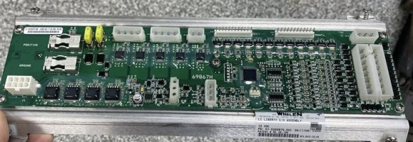
Here’s a photo of the board I got from the original eBay listing:
F7029243-B25C-4254-B627-5F783F9C92BB.jpeg

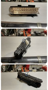
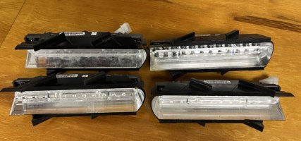
Here is a screenshot of the corner modules from their eBay listing, my specific ones are red so they aren’t the same in the photo but I think it’s the same model, and believe they are ballast:
BDDA0BF2-E006-4109-9D5D-7EF372420F1C.jpeg

I think based on the ballast and the corner modules, ballast is the way to go. I want to keep things simple and plug and play, I don’t need fancy passive tech on just the corners when the rest of the lightbar is simple 2007 tech. I just want a drop-in solution to have red LEDs flashing on the corners in the same fashion that the current strobes do.

Hope that helps.
 

shues

Lifetime VIP Donor
May 21, 2010
10,295
NW Indiana
Are you sure those are ballast corner modules? They don't have the fins of the heatsink that I usually associate with ballast corners.

The LC control board you have there is several years newer than Whelen's transition from ballast to passive technology.
 
  • Like
Reactions: Dave F

WS295

Member
May 31, 2012
28
NE, USA
Are you sure those are ballast corner modules? They don't have the fins of the heatsink that I usually associate with ballast corners.

The LC control board you have there is several years newer than Whelen's transition from ballast to passive technology.
My actual modules are dated 2005.
 

WS295

Member
May 31, 2012
28
NE, USA
A photo of when I had the bar apart for the LR11 install is the best I can do. I really just want the corners to go flash flash, hopefully using some combination of things I already have. As you can tell, I’m not an expert in this particular field.

C479EB9E-456D-4EC3-BF7A-D18DF940E812.jpeg
 

Dave F

Moderator
Sep 13, 2015
1,343
Berks County, PA
Deciphering all of this has been difficult

however, if i understand correct, you have a ballast IO, a ballast supply, but passive led heads

3 critical components are the PASSIVE setup are the io board, the heads and the wiring for PASSIVE systems

the older bars have FOUR components, all the above PLUS they need a ballast power supply

as such, the heads you have wont work, if you hooked them to the ballast supply it might burn the heads

displayed below ive gotten two pics, one of a ballast corner, and one of a passive corner

i hope this helps. having built many liberties, if you need further help Pm me


797C3012-362F-441B-9B64-306CE70094F9.jpeg
Above is a ballast head, as another member stated, not the elongated fins in the back which act as heat dispertion which is due partly to the draw/power of the head
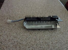
ECB24738-D3A9-487F-8B80-2039F4D5C909.jpeg
above is a passive head which is the type i suspect you have . note the shorter fins in the back, as passive heads require much less power which in turn means less heat for
the board to disperse
 

WS295

Member
May 31, 2012
28
NE, USA
That’s probably a function of this entire thing being difficult to decipher for me, with a lot of nuance and technical terms that I’m not finding immediately intuitive without having spent a lot of time in this stuff.

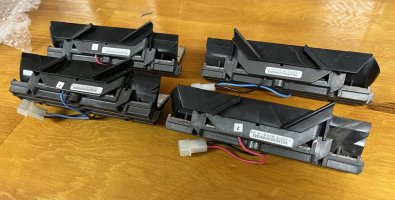
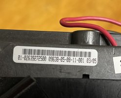
Here are the four actual corners I received today; all are dated 03/05. Don’t pay any attention to the blue positive wires, they’re rebuilt and I bench tested all four to confirm they’re red. Hoping this also helps to explain what I’m working with and what’s necessary to get where I need to be.

The board I have (which I posted a photo above from the eBay listing of) is labeled as follows: “LC Liberty 12V I/O Assembly P/N 01-0269879-00C”

533EF6AB-2553-457B-82F3-98F09E9C7BF0.jpeg
C586B94C-08FA-4C7E-A6E4-3C2FF28C4CD7.jpegC1ECB84F-9314-47D6-8DFA-4A08176DF231.jpeg
 

shues

Lifetime VIP Donor
May 21, 2010
10,295
NW Indiana
Based on the new photos, the corners you received appear to be passive corners. These can be connected to the LC I/O board, which it looks you have already installed. If my eyes don't deceive me, then you already have everything you need in place and there is no need to install the ballast.
 
  • Like
Reactions: Dave F

WS295

Member
May 31, 2012
28
NE, USA
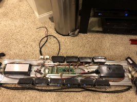
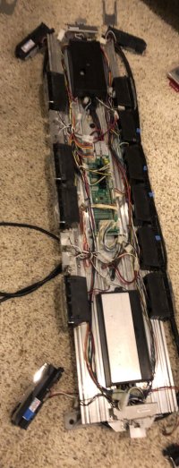
With the exception of the LR11 upgrades and adding the inner four modules on the back, the bar is pictured as I received it. My understanding is that the box on the left (driver) side is the corner strobe power supply and also serves to hold the bar together. I have to assume the LC I/O board you’re referring to is the exposed board in the middle between the strobe power box, and whatever is under the actual hollow ballast on the passenger side. However, I don’t see any open plugs on the board in the middle. Would the way I do this be to unplug the strobe black box (and leave as physical structural ballast or replace with a hollow ballast piece), and then plug the 4x2 pin corner module harness in to the I/O board assuming it would fit and replace one of those two 4x2 plugs currently in the top right of the board?

Think I’m starting to piece together now that the middle board is new tech, but for some reason they still had strobe corners and halogen floods on the bar in this era. So, I hope I’m following correctly that one of those 4x2 plugs goes to the strobe ballast on the left which inputs to the I/O board as ordinary LEDs, but somehow the strobe supply converts from LED language to strobe. So, if I’m understanding, the solution then would be to unplug everything to or from the strobe power supply, and just plug in and run the new two-pin corner harness, send it to the corners, put in the LEDs, and off I go. I can’t tell from my photo whether the 4x2 plugs look to be the same size as the connector I have pictured above on the left, but I do know the existing strobe connectors at the corners won’t work since they’re obviously 3-pin. I am a bit concerned by the existing 4x2 connectors appearing to have two plastic tabs on the ends, while my replacement one has one tab on the side.

So, if I can just plug the four corners into the control board in the middle, I think the question now is what that connection looks like.

74EA29FF-414D-48FC-B712-A7392D66AFE9.jpeg

Am I doing this right? Again, I appreciate everyone’s help here and just trying to get to the finish line on what seems to have been a pretty unusual and short-lived bar configuration by Whelen. Have a feeling this would be a lot easier if it had originally been just one kind of technology in the bar, as opposed to three (LED, strobe, halogen).

I already have the bar installed on my truck and want to do the homework now before I tear it apart; if I had it loose I’d definitely just pull it apart and figure out what makes it tick. But, since it’s already mounted, want to make sure I know where I’m going and what I’m doing to keep it simple and doable.
 

shues

Lifetime VIP Donor
May 21, 2010
10,295
NW Indiana
The open plugs for the corner modules are on the far end of the harnesses that the other LED lightheads are, presumably, connected to.
 

WS295

Member
May 31, 2012
28
NE, USA
Cool, guess I’ll just tear into it then. Anything special I need to do when disconnecting the strobe power pack after I remove the strobe corners?
 

shues

Lifetime VIP Donor
May 21, 2010
10,295
NW Indiana
I don't honestly remember. I have only owned a couple of patriots over the years and I have never attempted the conversion you have on your hands.
 

WS295

Member
May 31, 2012
28
NE, USA
Well, thanks again, I’ll just see how it goes and report back. I bought the bar originally because I liked the red lenses and the combination of strobe/halogen/LED, but since I’ve installed it I realized I liked LED takedowns and feeling less ridiculous with clear lenses. Plus, will be nice to be able to drive the truck into red police states without worrying about an impersonation charge.

Off to beer and tool time.
 

WS295

Member
May 31, 2012
28
NE, USA
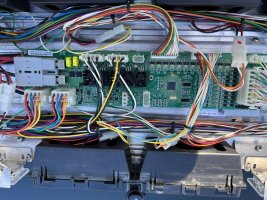
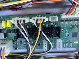
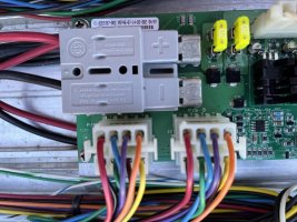
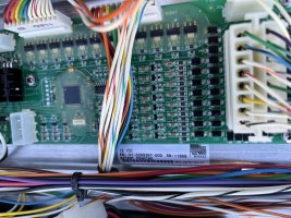
Alright, got busy taking the bar apart and unfortunately didn’t have great success. Photo dump inbound. The board in the middle doesn‘t have a corner output. I think killing the strobe power supply would be as simple as unplugging the connector labeled “P/S B,” but there was nowhere I could find to plug in the four-light harness I pictured above. The forward and rear connectors on the board each had twelve wires (six connectors), with two unused in the front, presumably for if you replaced your takedowns with flashing modules. I hate to think I’ve hit a dead end, but I kind of think I’ve hit a dead end unless someone knows the way forward here.

Overall board closeup:
7EB9EE3A-8E48-438A-88EC-1BDAE9ADA3A9.jpeg

Strobe power supply label:
5FB4D71D-CEA5-4A25-BC5F-E4F225D76B9F.jpeg

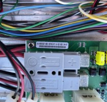
Center board label:
1C647B5B-EE6E-49E6-AA4C-B6AC5E83662C.jpeg

Board closeup 1:
57AB3CE8-D1F7-4D08-9C01-2E54DA630475.jpeg

Board closeup 2 (P/S B on the right goes to the strobe corner box, not fully sure where P/S A goes but I think to under the empty ballast on the right side):77DF5FA5-C3CE-4AC1-B234-1DB362D0221B.jpeg

Board closeup 3 showing the front and rear LED connectors and the label on the board:
20199C2B-68D2-4576-9D4B-E83049FA5492.jpeg

The worst case here is I live with white strobes on the ends or contact Whelen directly (because their technical sheet on Patriot strobe to LED conversion doesn’t seem to fully be matching up with my model), but figured I’d take one last shot here with the new info from digging into the bar today.
 

shues

Lifetime VIP Donor
May 21, 2010
10,295
NW Indiana
These close-up photos are very helpful. Along with the LC Liberty I/O board you purchased from eBay but have not yet installed, did you also get the LC Liberty internal wiring?
 

WS295

Member
May 31, 2012
28
NE, USA
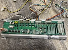
Here’s the loose board I have showing all the harnesses it came with plugged in:
6895702F-CAE3-42AF-9CA9-843B675B8D11.jpeg

I’m guessing you’re going to say really tear the bar apart, remove the strobe ballast, and then replace the existing board with the one above. Seems like a good solution since I’ll now have the corner connector in the bottom left, and everything else I should be able to keep the existing harnesses and just plug into the new board (front, rear, takedowns, alleys, the 16-pin big connector on the right (I’m assuming that’s the main control harness), and whatever the 3-pin above that is. If the power and control cables can just unplug and plug into the new board without having to undo all the installation and routing work I did in the vehicle, then that certainly shouldn’t be too bad.

Would an alternative be to just make a splitter on the four outermost inner LEDs plugs, and have them go to both those LEDs and the corners? I know the corners wouldn’t then flash independently.

But, seems like the best course of action here is take out the strobe ballast, existing I/O board, and replace with this new board and empty ballast where the strobe ballast was.
 
May 21, 2010
2,206
Elmira, ny
The 3 pin connector is for your traffic advisor, the right side connector is actually empty in case you wanna do a sync wire connection (plenty of youtube video explaining how to actually do a sync setup with your lightheads, its actually pretty cool)
 

WS295

Member
May 31, 2012
28
NE, USA
I should probably also note that the bar has (I think) 500-series TIR6s in back. It originally came with four in front and two in the back (with four filler plates) when I bought it, so I got four linear heads which I put in front and now have all 6 TIR6s in line in the back. Guessing that shouldn’t make a difference though and they’re functionally the same as far as the bar is concerned.

The big 16-pin connector on the right is for sync? Figured that was the main control harness since I’m not sure I’m seeing where else it would go and I think I remember the wire colors lining up with the end of the harness.

It will also still be fused for the original Patriot rating (40A I think), should I get a lower amp in-line fuse since I’m guessing the new Liberty configuration has a lower draw? Think it’d only matter in a fuse-blowing scenario but maybe it should blow lower than it did as a Patriot.
 

shues

Lifetime VIP Donor
May 21, 2010
10,295
NW Indiana
I cannot say whether the Patriot I/O board, which was designed to run 500-series 5mm LED lightheads, will handle the current requirements of a 500-series LIN6 plus a LIN12 corner on the same output.

I would suggest swapping out the Patriot I/O board for the Liberty I/O board, especially since you already own it. The Liberty I/O board is the same as the Freedom I/O board and so can accommodate doubling up on the number of heads per output with splitters. In fact, the Freedom came from the factory with splitters installed on all 400-series 6-over-6 lightheads.
 
  • Like
Reactions: WS295

WS295

Member
May 31, 2012
28
NE, USA
Oh, guessing EHFD meant the empty third pin on the right side of the TA connector.

Will swap in the Liberty board and replace the 40A fuse with a 30A one per Whelen’s instructions. Also will reuse as many of the harnesses as I can that are already inside the board (think that’ll be front, rear, takedowns, alleys, and obviously power and TA/the main control harness) to cut down on having to re-plug every single lighthead, and just remove all of the strobe dependent stuff, add the corner harness, and take it from there.

As far as knowing which corner plug goes where, is there an easy trick there? Seems like from looking at it that maybe the top row of four wires goes to one end, and the bottom row of four wires goes to the other.
 

WS295

Member
May 31, 2012
28
NE, USA
Whew, after a lot of work, got the strobe ballast and old board out, new board in, everything hooked up, cables managed, and the whole bar buttoned back up. It’s a very lucky thing that I 1. have my bar mounted on a back rack, and 2. left myself a few feet coiled up on the control harness when I installed it. Loosening the ballast stop screw from the bottom would’ve been impossible otherwise, as would have been getting the main harness plug free of the board without the extra to get it hanging out the side so the board could slide over the cable.

After I sealed everything up and put in a new 30A fuse to replace the 40A one (though it seems like some manuals say 20A for the LC Liberty so I’m even wondering if I should go down to 20A), tested my alley and takedown switches - all good. Tested my main flashing mode switch and didn’t have a lot of the functions I did before, and same for my TA switches - my left one flashed two modules in the back, my right one did nothing.

Looked up the install manual for an LC Liberty, which quickly explained why because almost all the wires are new functions now, and it explained why my old wiring configuration was doing weird things with the new board. However, my old main switch wiring did bring in the corners, so all good there. Once I rewire my switches, should be golden.

Thanks again for the help and helping me make sense of this.

New board and ballast in and wires managed as best I could:
010D0200-E477-4C8F-82C8-72B473442D64.jpeg
 
  • Like
Reactions: firebuff17

Forum Statistics

Threads
54,121
Messages
450,345
Members
19,166
Latest member
helmi

About Us

  • Since 1997, eLightbars has been the premier venue for all things emergency warning equipment. Discussions, classified listings, pictures, videos, chat, & more! Our staff members strive to keep the forums organized and clutter-free. All of our offerings are free-of-charge with all costs offset by banner advertising. Premium offerings are available to improve your experience.

User Menu

Secure Browsing & Transactions

eLightbars.org uses SSL to secure all traffic between our server and your browsing device. All browsing and transactions within are secured by an SSL Certificate with high-strength encryption.