Cannon Hyperflash and a Resistor

thekameleon

Member
Jul 19, 2013
95
Illinois
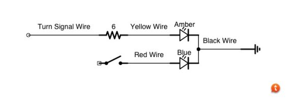
So I got my cannons (amber/Blue) With Amber overriding the blue in my turn signal housing. I initially got a hyperflash, knowing this could be likely, I added a 6 ohm 50w resisitor across the turn signal and ground... Now the Blue and Amber seems to be strobing when the turn signal is on probably around 13 to 14 hz. It almost looks white coming out like a bad florescent bulb... Any ideas?
 
Apr 28, 2012
1,042
Knox County, ME
Remove the resistor and purchase a led flasher. There are a couple companies that make replacement OEM flasher for all led turn signals
 

Carlos SpicyWeiner

Lifetime VIP Donor
May 3, 2012
5,233
Lakeland, Florida
the resistor is negatively affecting the flasher of the cannon.
 

bshockme

Member
May 26, 2010
60
Missouri
The resistor is reducing the voltage to the cannon. I would guess that when the amber activates, it pulls down the voltage below the threshold of activation, deactivating the amber circuit. Voltage increases due to no load, and the process repeats. This is a simple explanation for what is likely a more complex electrical occurrence, but none the less, it appears to be what is happening. suggest as others have, replace the flasher with a solid state constant rate flasher, or a led flasher, and remove the resistor.
 

thekameleon

Member
Jul 19, 2013
95
Illinois
bshockme said:
The resistor is reducing the voltage to the cannon. I would guess that when the amber activates, it pulls down the voltage below the threshold of activation, deactivating the amber circuit. Voltage increases due to no load, and the process repeats. This is a simple explanation for what is likely a more complex electrical occurrence, but none the less, it appears to be what is happening. suggest as others have, replace the flasher with a solid state constant rate flasher, or a led flasher, and remove the resistor.

Not reducing the voltage at all. I checked it. The resistor is wired in parallel.


Anyway on to the Solid State Flasher. Anyone know first where the turn signal flasher is on an Explorer and second which one it is... There seem to be many out there and I can't find any documentation on the model/type used in the Explorer.
 

Steve0625

Member
Jun 23, 2010
1,213
Northville NY
thekameleon said:
Not reducing the voltage at all. I checked it. The resistor is wired in parallel.

Anyway on to the Solid State Flasher. Anyone know first where the turn signal flasher is on an Explorer and second which one it is... There seem to be many out there and I can't find any documentation on the model/type used in the Explorer.
What model year on the Explorer? If it is fairly recent, it likely has a BCM/PCM computer system. There is no flasher; it's all done by the computer. And that would be why you are having issues with Cannons as turn signals.


Is this fronts or rears? My '12 Super Duty was factory programmed so that the front turn signals require incandescent lamps, but the rear ones are not. I can have the fronts reprogrammed for LED's but the programming cost is well north of $100. Not worth it in my book.


If you're doing the rears only and your Explorer has trailer tow wiring, you can tap that and drive the Cannons normally. Trailer tow is relay driven from the PCM so there's no bulb out sensing.
 

sheazle

Member
May 31, 2013
185
Missouri
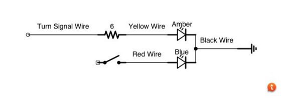
The resistor has to be in series. That way your computer sees the correct amount of current and thinks the bulb is good.


Put the resistor on the positive side between the vehicle and the cannon. Leave your alternate color (blue) to get full 12v and do not put a resistor between the cannon ground wire and vehicle ground.


aimg.tapatalk.com_d_14_04_08_9epagadu.jpg


Edit: added a diagram
 
Last edited by a moderator:

thekameleon

Member
Jul 19, 2013
95
Illinois
sheazle said:
The resistor has to be in series. That way your computer sees the correct amount of current and thinks the bulb is good.

Put the resistor on the positive side between the vehicle and the cannon. Leave your alternate color (blue) to get full 12v and do not put a resistor between the cannon ground wire and vehicle ground.


aimg.tapatalk.com_d_14_04_08_9epagadu.jpg


Edit: added a diagram

Series?. Wouldn't that drop the voltage to the Cannon? Everywhere I see this documented it states to wire in parallel. How much of a voltage drop would a 6 ohm resistor produce? I just want ot make sure I get this right.
 

sheazle

Member
May 31, 2013
185
Missouri
It isn't much voltage drop with only 6 ohms. Barely affects the brightness, and cannons are super bright for turn signals anyway.
 

thekameleon

Member
Jul 19, 2013
95
Illinois
Steve0625 said:
What model year on the Explorer? If it is fairly recent, it likely has a BCM/PCM computer system. There is no flasher; it's all done by the computer. And that would be why you are having issues with Cannons as turn signals.

Is this fronts or rears? My '12 Super Duty was factory programmed so that the front turn signals require incandescent lamps, but the rear ones are not. I can have the fronts reprogrammed for LED's but the programming cost is well north of $100. Not worth it in my book.


If you're doing the rears only and your Explorer has trailer tow wiring, you can tap that and drive the Cannons normally. Trailer tow is relay driven from the PCM so there's no bulb out sensing.

Sigh... it is indeed a 2013 Explorer. I have switch back LEDs to the front which have worked fine in the past with a 6 ohm resistor wired in parallel. Now I have added the Cannon and I get a rapid flash (I wouldn't say hyper, but it is faster then what it was)


So these BCMs can be reprogrammed? Who would do this? I have a feeling this would void the warranty wouldn't it?
 

sheazle

Member
May 31, 2013
185
Missouri
thekameleon said:
Series?. Wouldn't that drop the voltage to the Cannon? Everywhere I see this documented it states to wire in parallel. How much of a voltage drop would a 6 ohm resistor produce? I just want ot make sure I get this right.

So going back to actually doing the math, the voltage drop I am getting with 6 ohms in series with a cannon is about 3-4v. The cannon is getting 9v, which for me is perfect for my turn signals, brighter than the 3157 it replaced, but not so bright as the cannon on full power. I am using the same cannon for my parking lights (with diodes to prevent backfeeding) through 30 ohms. I found the cannons dim very well from ~6.5-12v.


As far as the resistor making the computer think it has a bulb...I have no idea, it actually shouldn't make a difference, but for my 2010 F150 it wouldn't work in parallel so I put it in series and hyperflash went away. Cannons are a little picky about having a good ground also, so check your connection there if it isn't working properly.
 

Steve0625

Member
Jun 23, 2010
1,213
Northville NY
thekameleon said:
Sigh... it is indeed a 2013 Explorer. I have switch back LEDs to the front which have worked fine in the past with a 6 ohm resistor wired in parallel. Now I have added the Cannon and I get a rapid flash (I wouldn't say hyper, but it is faster then what it was)

So these BCMs can be reprogrammed? Who would do this? I have a feeling this would void the warranty wouldn't it?
The Ford dealer can do it. I know that it is an easy fix for using LED's in place of incandescents. All they do is change the programming to ignore the low/no current "bulb out" sensing. It also negates the need for the resistors. But as I pointed out, it's very expensive. Several guys in the Ford Truck Forum reported dealer charges of $120 and greater for this change.


You will have to ask the dealer about warranty issues.


Once the programming is changed, the Cannons should perform fine as turn signals without the need for a resistor. They'll be uber bright though; maybe too bright for turn signals.


I have Cannons in place of the standard reverse lights on my truck. Unlike turn signals, the extra brightness of them is just like having auxiliary backup lights. It's great.
 

thekameleon

Member
Jul 19, 2013
95
Illinois
sheazle said:
So going back to actually doing the math, the voltage drop I am getting with 6 ohms in series with a cannon is about 3-4v. The cannon is getting 9v, which for me is perfect for my turn signals, brighter than the 3157 it replaced, but not so bright as the cannon on full power. I am using the same cannon for my parking lights (with diodes to prevent backfeeding) through 30 ohms. I found the cannons dim very well from ~6.5-12v.

As far as the resistor making the computer think it has a bulb...I have no idea, it actually shouldn't make a difference, but for my 2010 F150 it wouldn't work in parallel so I put it in series and hyperflash went away. Cannons are a little picky about having a good ground also, so check your connection there if it isn't working properly.

I tried it in series... No luck
 

thekameleon

Member
Jul 19, 2013
95
Illinois
Steve0625 said:
The Ford dealer can do it. I know that it is an easy fix for using LED's in place of incandescents. All they do is change the programming to ignore the low/no current "bulb out" sensing. It also negates the need for the resistors. But as I pointed out, it's very expensive. Several guys in the Ford Truck Forum reported dealer charges of $120 and greater for this change.

You will have to ask the dealer about warranty issues.


Once the programming is changed, the Cannons should perform fine as turn signals without the need for a resistor. They'll be uber bright though; maybe too bright for turn signals.


I have Cannons in place of the standard reverse lights on my truck. Unlike turn signals, the extra brightness of them is just like having auxiliary backup lights. It's great.

OK I will do this then... It would be nice if Ford could make this a setting... Do you know what the price ranges were? And do note, I am not getting a bulb out error just a fast flash.
 

Steve0625

Member
Jun 23, 2010
1,213
Northville NY
thekameleon said:
OK I will do this then... It would be nice if Ford could make this a setting... Do you know what the price ranges were? And do note, I am not getting a bulb out error just a fast flash.
I've already said twice in this thread that I heard prices of $100 and more to reprogram the computer.


Fast flash is a bulb out indicator on newer cars with computer systems.
 

thekameleon

Member
Jul 19, 2013
95
Illinois
Steve0625 said:
I've already said twice in this thread that I heard prices of $100 and more to reprogram the computer.


Fast flash is a bulb out indicator on newer cars with computer systems.

Got it thanks... And for the attitude as well
 

Steve0625

Member
Jun 23, 2010
1,213
Northville NY
thekameleon said:
Got it thanks... And for the attitude as well
I stated cost in my first response to the thread.


You asked cost which I then answered directly.


While you quoted me both times, I can only guess that when you asked yet again, you did not actually read what I posted.


You might want to look in the mirror on the attitude issue.
 

thekameleon

Member
Jul 19, 2013
95
Illinois
Steve0625 said:
I stated cost in my first response to the thread.

You asked cost which I then answered directly.


While you quoted me both times, I can only guess that when you asked yet again, you did not actually read what I posted.


You might want to look in the mirror on the attitude issue.

Sherlock I asked for a range... You said 100 on up... All I wanted to know was the upper range... Maybe you should try getting hooked on phonics and basic reading comprehension


P.S. I already know I have an attitude, I embrace it
 

thekameleon

Member
Jul 19, 2013
95
Illinois
Im over it already.


Anyway... This challenge bothers me... So I dug through some other forums and I found this quote about the draw on the cannons:


"Kd8bao, your multimeter/voltage meter/continuity tester... (100 names for them) is way off. (or you have it at the wrong setting)


We will be coming out with a data sheet regarding the Cannon soon. See this link regarding the 6 LED/T6:
http://www.feniex.com/literature/T6-...1750157224.pdf


In the mean time the average current draw for the Cannon is around 500mA for 6 LED and 1Amp for 12 LEDs, which is 50% duty cycle (aka flashing). If you run the lights at steady burn they will measure double the current mentioned.


-Gary "


This means since I have it in steady on, it is pulling 1 amp with 6 LED,s which is 12 watts of power... A single 6 ohm resistor in parallel maybe allowing too much current to pass. So what if I took two resistors wired in series and wired that set in parallel. That would be 12 ohms which would account for 1 amp or 12 watts which I think produce enough of a load right???? Someone please tell me if my kung fu is not strong (i.e. my logic is flawed)
 

ERM

Member
May 22, 2010
720
Omaha, NE
With regards to this thread, there are many misleading statements being made which is causing more confusion than understanding. Resistors, by themselves, reduce current, not voltage.


Picture it this way, when you're watering a plant with a garden hose, you pull the trigger slightly, reducing the amount of resistance in the nozzle to allow water to exit. The more you pull the handle, the less resistance there is on the water, and the more water pressure exits. No resistance allows for maximum current.


When a resistor is connected in series, the current is reduced. If you're looking to lower voltage, then you need to create a voltage divider using two resistors. Just Google that term and you'll find plenty of diagrams and formulas.


In your setup, you've installed a pull down resistor. With such a low Ohm rating, you are more than likely shunting power away from the Cannon. Also, you have not taken into consideration how the Cannon works or the circuitry in the driver. What are the ratings of the voltage regulator or the LED drivers? What is the BCM doing when it senses your resistor setup? What wattage resistor are you using?


With respect to your setup, you're trying to understand why the lights are behaving in this manner and can't derive a logical conclusion based on what SHOULD be happening. The problem is that you are not connected to a constant DC source where these rules apply. You are connected to the vehicle's BCM, where you have no idea what has been programmed to occur when the factory presets are changed. Everyone is throwing out suggestions based on power coming from an electronic flasher.


These vehicles are getting more and more complicated. It's getting harder to "fool" the BCM because the BCM is being programmed to react differently to changing conditions.


Have you taken into consideration as to where the ground is going from the 3157? Does it go back into to the BCM for it's voltage reference signaling a bulb out (or something similar) condition? Without knowing the circuit you are modifying, don't expect typical results. Hopefully this will help ease some of your frustrations of not understanding why you're not seeing typical results.


Tony
 

thekameleon

Member
Jul 19, 2013
95
Illinois
ERM said:
With regards to this thread, there are many misleading statements being made which is causing more confusion than understanding. Resistors, by themselves, reduce current, not voltage.

Picture it this way, when you're watering a plant with a garden hose, you pull the trigger slightly, reducing the amount of resistance in the nozzle to allow water to exit. The more you pull the handle, the less resistance there is on the water, and the more water pressure exits. No resistance allows for maximum current.


When a resistor is connected in series, the current is reduced. If you're looking to lower voltage, then you need to create a voltage divider using two resistors. Just Google that term and you'll find plenty of diagrams and formulas.


In your setup, you've installed a pull down resistor. With such a low Ohm rating, you are more than likely shunting power away from the Cannon. Also, you have not taken into consideration how the Cannon works or the circuitry in the driver. What are the ratings of the voltage regulator or the LED drivers? What is the BCM doing when it senses your resistor setup? What wattage resistor are you using?


With respect to your setup, you're trying to understand why the lights are behaving in this manner and can't derive a logical conclusion based on what SHOULD be happening. The problem is that you are not connected to a constant DC source where these rules apply. You are connected to the vehicle's BCM, where you have no idea what has been programmed to occur when the factory presets are changed. Everyone is throwing out suggestions based on power coming from an electronic flasher.


These vehicles are getting more and more complicated. It's getting harder to "fool" the BCM because the BCM is being programmed to react differently to changing conditions.


Have you taken into consideration as to where the ground is going from the 3157? Does it go back into to the BCM for it's voltage reference signaling a bulb out (or something similar) condition? Without knowing the circuit you are modifying, don't expect typical results. Hopefully this will help ease some of your frustrations of not understanding why you're not seeing typical results.


Tony

All excellent points Tony and I believe you are right, I am shunting power away from the cannon. I did notice that all the grounds from the turn, reverse and even the OEM LED brake lights are all connecting together. So I don't think the BCM is monitoring the ground for a reference voltage.


I am using 50watt resistors at 6 ohms. I am thinking since the Cannon already pulls around 12 watts that I should probably use a resistor that is about 12 to 15 ohms at 25 watts to 50 watts. This would then equal about 25 watts of load which I think should "fool" the BCM.


The typical LED Turn signal does not pull 12 watts more like 3 or 4, hence why 6 ohms may allow too much current to pass and as you said shunt the power away creating the weird cannon behavior.


In the end, I don't know enough about the Cannon circuitry or the BCM circuitry. Neither manufacture I think will volunteer that information to help make good choices due to liability reasons. So it is an experiment til then. I will let you know what the results are with the two 6 ohm resistors in series are later today.
 

MtnMan

Member
Dec 20, 2012
1,533
Eastern PA
ERM said:
With regards to this thread, there are many misleading statements being made which is causing more confusion than understanding. Resistors, by themselves, reduce current, not voltage.

Sorry, but that's only confounding the confusion. Current and voltage are related. Reducing current will reduce voltage in a linear circuit.


Anyway, this is getting pretty far afield from the original topic. My suggestion to the OP is to go back to standard lamps in the front signals.
 

thekameleon

Member
Jul 19, 2013
95
Illinois
MtnMan said:
Sorry, but that's only confounding the confusion. Current and voltage are related. Reducing current will reduce voltage in a linear circuit.

Anyway, this is getting pretty far afield from the original topic. My suggestion to the OP is to go back to standard lamps in the front signals.

That means give up... Not in my nature. Plus I would need new housing as I had to retrofit the cannons to fit.


*** Updates ***


I tried the two resistors in series that is wired parallel to the cannon and that did not work.


So I connected everything back up the way it was and I called my local Ford dealership... Their answer, "we don't know if we can. Come on in and lets find out."


However, on my way to work I discovered something interesting... My turn signal suddenly behaved normally. How can this be? Well I looked at my radar detector which monitors my vehicles voltage and I noticed it was registering 13.3 volts... Typically my Explorer will range between 14.8 and 13.1. I am unsure why the fluctuation but it hasn't created a problem yet. I assume it is by design. When the voltage went up to ~13.9 volts, the turn signal started to hyper flash. When it went down past ~13.9, it acted normal. It may not mean anything, but I thought I toss it out there
 

ERM

Member
May 22, 2010
720
Omaha, NE
MtnMan said:
Sorry, but that's only confounding the confusion. Current and voltage are related. Reducing current will reduce voltage in a linear circuit.

Anyway, this is getting pretty far afield from the original topic. My suggestion to the OP is to go back to standard lamps in the front signals.

My attempts here are to keep everyone from throwing out random suggestions. Does voltage go down with a single resistor, yes it does, but not in the same way as using two resistors in the voltage divider circuit I mentioned. A resistor's primary function is to limit the flow of an electrical current. Is this not a true statement? My point was to help people get a better understanding of what they were attempting to do. You would NOT use a single resistor to drop voltage in this instance.


I was waiting to see how long it was going to take for someone to try and correct what I was suggesting. Many people understand the basics of electronics, which for installation purposes is more than enough, but don't have the training or equipment to see all the "other" things going on in an electrical circuit. My explanations are for the tasks we are seeking to do. The engineers at the manufacturers work out all the nitty gritty stuff in the circuit. They just minimize the amount of variables we have to worry about.


Could I get all technical and spout all of the engineering jargon? Yes I could, but I would lose the majority of my audience. This isn't the physics forum. We just want our lights to work. :yes:
 

thekameleon

Member
Jul 19, 2013
95
Illinois
ERM said:
My attempts here are to keep everyone from throwing out random suggestions. Does voltage go down with a single resistor, yes it does, but not in the same way as using two resistors in the voltage divider circuit I mentioned. A resistor's primary function is to limit the flow of an electrical current. Is this not a true statement? My point was to help people get a better understanding of what they were attempting to do. You would NOT use a single resistor to drop voltage in this instance.

I was waiting to see how long it was going to take for someone to try and correct what I was suggesting. Many people understand the basics of electronics, which for installation purposes is more than enough, but don't have the training or equipment to see all the "other" things going on in an electrical circuit. My explanations are for the tasks we are seeking to do. The engineers at the manufacturers work out all the nitty gritty stuff in the circuit. They just minimize the amount of variables we have to worry about.


Could I get all technical and spout all of the engineering jargon? Yes I could, but I would lose the majority of my audience. This isn't the physics forum. We just want our lights to work. :yes:

I appreciate your input ERM. So I looked at the voltage divide and it seems simple enough, but here is my question. Would I need a second resistor or would the Cannon itself be that resistor? And then my next question is what size resistors (R1, and R2) would be appropriate here. I am thinking if I get 13 or less volts at the cannon. I am good to go (at least the BCM thinks so). From the other post I saw 6 LEDs are consuming one amp of current. So my initial thought would be to take a 3 ohm resistor at R1 and 12 ohm at R2. I look forward to your feedback and thanks again.
 

ERM

Member
May 22, 2010
720
Omaha, NE
thekameleon said:
I appreciate your input ERM. So I looked at the voltage divide and it seems simple enough, but here is my question. Would I need a second resistor or would the Cannon itself be that resistor? And then my next question is what size resistors (R1, and R2) would be appropriate here. I am thinking if I get 13 or less volts at the cannon. I am good to go (at least the BCM thinks so). From the other post I saw 6 LEDs are consuming one amp of current. So my initial thought would be to take a 3 ohm resistor at R1 and 12 ohm at R2. I look forward to your feedback and thanks again.

After taking a look at my Cannons, I found that on steady burn, they draw .9 amps, but when off, measure 0 ohms resistance.


What I believe is happening is that without the resistor, the vehicle is monitoring the circuit. When it sees nothing, it then runs the program for a quick flash to signify there is a bulb out. When you activate your circuit with the low Ohm resistor, I believe the low resistance in shunting power away from the Cannon. Not knowing how picky the Cannon might be, this may be a problem.


Now, you're asking me to speculate, so I would try one of the following suggestions. The first is to add a resistor to ground in the realm of about 10k Ohms. The vehicle will still see a resistance, but will be enough of a resistance to not mess with the Cannon.


The second alternative is to install a small bulb across the positive wire to ground. Your resistance would still be there and the light would glow when turned on. Being in the engine compartment, it won't make a difference as to lighting anything up. That would be my best guess as for things to try.


Without being there and taking measurements myself, it's hard to make suggestions in the blind. But this would be some of the things I would try. Let me know your findings.


Tony
 

Carlos SpicyWeiner

Lifetime VIP Donor
May 3, 2012
5,233
Lakeland, Florida
I've often relied on Tony's technical knowledge to help me.


In stupider terms, we did an install on the new silverado. The Silverado has a total of four parking lamps to the front (two on each side), one of which is a turn signal. We replaced the turn signal bulb with a Cannon. At times it would not indicate a turn signal bulb was out but other times it would. So I converted the second turn parking light bulb to a cannon making a total of 3 on each turn signal circuit (2 front, 1 rear). We now do not get that indication anymore and customer has a bunch of warning to the front.


Not sure if you'd want to add one surface mounted somewhere as a marker light and side turn signal. But that might help (since we are throwing out options). Obviously you could easily test this theory prior to doing it.
 

thekameleon

Member
Jul 19, 2013
95
Illinois
ERM said:
After taking a look at my Cannons, I found that on steady burn, they draw .9 amps, but when off, measure 0 ohms resistance.

What I believe is happening is that without the resistor, the vehicle is monitoring the circuit. When it sees nothing, it then runs the program for a quick flash to signify there is a bulb out. When you activate your circuit with the low Ohm resistor, I believe the low resistance in shunting power away from the Cannon. Not knowing how picky the Cannon might be, this may be a problem.


Now, you're asking me to speculate, so I would try one of the following suggestions. The first is to add a resistor to ground in the realm of about 10k Ohms. The vehicle will still see a resistance, but will be enough of a resistance to not mess with the Cannon.


The second alternative is to install a small bulb across the positive wire to ground. Your resistance would still be there and the light would glow when turned on. Being in the engine compartment, it won't make a difference as to lighting anything up. That would be my best guess as for things to try.


Without being there and taking measurements myself, it's hard to make suggestions in the blind. But this would be some of the things I would try. Let me know your findings.


Tony

Quick question when you say at a 10K resistor to ground do you mean in parallel to the cannon?
 

ERM

Member
May 22, 2010
720
Omaha, NE
thekameleon said:
Quick question when you say at a 10K resistor to ground do you mean in parallel to the cannon?

Your turn signal wire is connected to your Cannon. Connect a resistor to this wire and connect the other end of the resistor to ground.
 

bluestinger90

Member
Jun 5, 2010
657
BC / California
I've often relied on Tony's technical knowledge to help me.


In stupider terms, we did an install on the new silverado. The Silverado has a total of four parking lamps to the front (two on each side), one of which is a turn signal. We replaced the turn signal bulb with a Cannon. At times it would not indicate a turn signal bulb was out but other times it would. So I converted the second turn parking light bulb to a cannon making a total of 3 on each turn signal circuit (2 front, 1 rear). We now do not get that indication anymore and customer has a bunch of warning to the front.


Not sure if you'd want to add one surface mounted somewhere as a marker light and side turn signal. But that might help (since we are throwing out options). Obviously you could easily test this theory prior to doing it.

This is the best (and more costly solution) to replicating the OEM bulbs properties. Add more leds!
 

Carlos SpicyWeiner

Lifetime VIP Donor
May 3, 2012
5,233
Lakeland, Florida
holy thread from the dead
 

chucksorce

Member
Aug 3, 2014
236
nj
I'm glad this was brought back from the dead because I can use some good info from the gurus, I have a 14 ram 2500 which has LED taillights but incandescent reverse lights. I'm installing 3 mode cannons in place of the reverse lamps because of the design of my taillights it's the only place I can put the cannon, obviously I'm going to use the cannon as my reverse light but my truck monitors my reverse lamps so when I remove the incandescent bulbs I get a lamp out message. I was told to go to Radio Shack and get 10 ohm ceramic resistors and put them in parallel on my reverse light circuit, well I did that and in still getting a lamp out message. Any ideas why the resistor isn't going the job?
 

Carlos SpicyWeiner

Lifetime VIP Donor
May 3, 2012
5,233
Lakeland, Florida
I'm glad this was brought back from the dead because I can use some good info from the gurus, I have a 14 ram 2500 which has LED taillights but incandescent reverse lights. I'm installing 3 mode cannons in place of the reverse lamps because of the design of my taillights it's the only place I can put the cannon, obviously I'm going to use the cannon as my reverse light but my truck monitors my reverse lamps so when I remove the incandescent bulbs I get a lamp out message. I was told to go to Radio Shack and get 10 ohm ceramic resistors and put them in parallel on my reverse light circuit, well I did that and in still getting a lamp out message. Any ideas why the resistor isn't going the job?
Probably not getting providing enough of a load for the canbus to think the bulb is still in place.
 

Forum Statistics

Threads
54,187
Messages
450,565
Members
19,189
Latest member
Jesseclark2448

About Us

  • Since 1997, eLightbars has been the premier venue for all things emergency warning equipment. Discussions, classified listings, pictures, videos, chat, & more! Our staff members strive to keep the forums organized and clutter-free. All of our offerings are free-of-charge with all costs offset by banner advertising. Premium offerings are available to improve your experience.

User Menu

Secure Browsing & Transactions

eLightbars.org uses SSL to secure all traffic between our server and your browsing device. All browsing and transactions within are secured by an SSL Certificate with high-strength encryption.