I'm looking for documentation (wiring, setup) manuals I've looked for well over 4 hours and have found nothing.
You are using an out of date browser. It may not display this or other websites correctly.
You should upgrade or use an alternative browser.
You should upgrade or use an alternative browser.
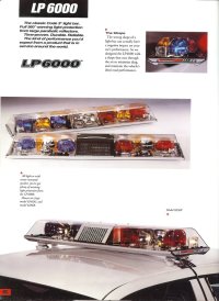
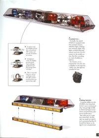
Code 3 Force 4 LP
- Thread starter NLACo
- Start date
Installation or sales stuff? They basically have a metal frame that serves as a ground via the black wire and every other wire either does a feature or isn't used. You had mini and full sized take downs, mini alleys, full sized flashers and the metal rotators later turned plastic and "not great". They were a platform for the multi-function "stingray" rotator.I'm looking for documentation (wiring, setup) manuals I've looked for well over 4 hours and have found nothing.
They are literally a "ground the big black wire and start putting 12v to the others and label as you go" project. There is no standard setup other than black ground to the frame, test the other colors.
Attachments
Installation. I have a bar but it didn't come with any wires and I'm trying to figure out how to rewire it along with what wire controls what.Installation or sales stuff? They basically have a metal frame that serves as a ground via the black wire and every other wire either does a feature or isn't used. You had mini and full sized take downs, mini alleys, full sized flashers and the metal rotators later turned plastic and "not great". They were a platform for the multi-function "stingray" rotator.
They are literally a "ground the big black wire and start putting 12v to the others and label as you go" project. There is no standard setup other than black ground to the frame, test the other colors.
So essentially you need a harness that has one main ground, connect that to the frame of the bar just inside the hole where the harness enters with a decent sized screw and make sure there is good contact. A harness with a 10 gauge black should be good. Then there should be little terminal blocks at/behind each feature. Those should each have two screws and be ganged together, or not. Each feature (rotator, flasher, takedown etc) will have one. You run the other wires (+12v) to each one of those terminal blocks. Often there are runner wires between features such as both inner or outer rotators (so the main red wire might got to first one rotator then an internal red wire runs to the other rotators). That would mean a wire between them so they function together. A common setup is red powers both outer rotators, red with a stripe (white or black) runs the inboard rotators. The yellow, green, blue, white etc run other functions like takedowns or flashers. It's honestly up to you and Code 3 never really had a standard because you could set these up hundreds of ways. The big thing is all the features either ground to the frame via their mounting screws or have a black wire coming off of them that is screwed to the frame. To summarize; you need a harness with a big ground wired to the frame, and smaller colored wires to the black terminal blocks behind each feature any way you see fit. To test, ground the frame and start putting 12vdc+ to the terminal blocks behind the rotators etc.Installation. I have a bar but it didn't come with any wires and I'm trying to figure out how to rewire it along with what wire controls what.

Thank you for the help!So essentially you need a harness that has one main ground, connect that to the frame of the bar just inside the hole where the harness enters with a decent sized screw and make sure there is good contact. A harness with a 10 gauge black should be good. Then there should be little terminal blocks at/behind each feature. Those should each have two screws and be ganged together, or not. Each feature (rotator, flasher, takedown etc) will have one. You run the other wires (+12v) to each one of those terminal blocks. Often there are runner wires between features such as both inner or outer rotators (so the main red wire might got to first one rotator then an internal red wire runs to the other rotators). That would mean a wire between them so they function together. A common setup is red powers both outer rotators, red with a stripe (white or black) runs the inboard rotators. The yellow, green, blue, white etc run other functions like takedowns or flashers. It's honestly up to you and Code 3 never really had a standard because you could set these up hundreds of ways. The big thing is all the features either ground to the frame via their mounting screws or have a black wire coming off of them that is screwed to the frame. To summarize; you need a harness with a big ground wired to the frame, and smaller colored wires to the black terminal blocks behind each feature any way you see fit. To test, ground the frame and start putting 12vdc+ to the terminal blocks behind the rotators etc.
No problem, if you run into specific issues post with a picture if you can. These are one of the easier bars to work on especially since they frame ground and use metal parts, but they can appear daunting if you are starting from scratch. Enjoy the project!Thank you for the help!
One thing i noticed is the xl5000 and 9000 are wired just about the same as the lp6000, if you have either of those bars then just look at how the wires go ")
One thing i noticed is the xl5000 and 9000 are wired just about the same as the lp6000, if you have either of those bars then just look at how the wires go
This is a good point. The LP was basically a "Low Profile" version of the "Xtra Large" XL. The metal frame ground and terminal blocks for each feature made them very easy to customize. The most confusing part would be the multi-function stingray rotators which had several generations. Sometimes a 700 series flasher would be wired in an odd way to flash the takedowns or something. In their prime both bars offered very similar options with there being only a few features that didn't fit in the LP.
It's important to note that the XL had a sealed beam version first and these bars are a little more complex as far as how current gets to the bulbs because the bulbs themselves actually rotate vs just the reflector. You would sometimes see problems between the assemblies and the copper contacts they spun on or the contacts would short to the frame.
In their prime (when halogen bulbs and metal reflectors were used) both bars were pretty effective and easy to service.