I know I have CAPs around, I'll give them a swap. They whole thing smells/stinks like a ruptured cap to me but I can find no evidence of one.First thing to try is known working caps. These do have screw terminials...some of 'em, you have to desolder which is a slight PITA.
You are using an out of date browser. It may not display this or other websites correctly.
You should upgrade or use an alternative browser.
You should upgrade or use an alternative browser.
Old Whelen Power Supplies
- Thread starter JohnMarcson
- Start date
Here are some spare edge supplies I have, the newer ones are all potted and not very interesting. The oldest one has the outputs on the board, it is double flash. The other non-potted one has an output pigtail and is comet flash. The newest ones are multip-pattern.


The one modern potted power supply that stands out to me is the UB412

This is the only PS I know of that Whelen made where the controller sends flash port/timing data in real time to the PS. It could be used as a conventional PS with limited patterns - but if you hooked up to the 2-wire RS485 interface and sent the right numbers to it, you could make it flash however you wanted.
I gather this was necessary for the ULTRA bars where three PSs worked together to form a whole-bar pattern.
BL10000s did this before the UB412/ULTRA, but the BL10000 didn't use simple RS485 messaging to do it (instead, direct shift-register low-level electronics were used).
That is interesting... I forgot it even came from an ultra bar, but it obviously did.The one modern potted power supply that stands out to me is the UB412
View attachment 236528
This is the only PS I know of that Whelen made where the controller sends flash port/timing data in real time to the PS. It could be used as a conventional PS with limited patterns - but if you hooked up to the 2-wire RS485 interface and sent the right numbers to it, you could make it flash however you wanted.
I gather this was necessary for the ULTRA bars where three PSs worked together to form a whole-bar pattern.
BL10000s did this before the UB412/ULTRA, but the BL10000 didn't use simple RS485 messaging to do it (instead, direct shift-register low-level electronics were used).


Here's a DOT-94C manufactured around '97 (based on components' date codes). The board itself bears a copyright of 1993!
As you can see, some bozo replaced the original Motorola micro controller with a hacked-in Microchip MCU (PIC16F893) but that might help make a point.
This PS demonstrates the transition from old-school low-level ICs to "intelligent" microcontroller-based power supplies. This opened the door for these devices to interact with a network (i.e. B-LINK) as well as allowed for a variety of flash patterns.
This came in a set of DOT stuff I bought, it was the only non-working one. The capacitor mounts are broken which isn't common, but I don't think that's why it isn't working. It makes a very fast clicking sound when powered up. It was connected to a pair of micro edges with two linear "corner" tubes in each (4 total). Notice there is no "head select" wire, it is either on or off.
I did get a few 94Cs and a UPS64 double flash and a UPS64C comet flash supply in the lot as well as some misc newer stuff, so it was worth it.


I did get a few 94Cs and a UPS64 double flash and a UPS64C comet flash supply in the lot as well as some misc newer stuff, so it was worth it.
Yes, the Austin Model "-RS-" -- it has the same board as Whelen UPS52 but no options are built out (no head selection, no low-power). I think we covered that on PG 1 here.This came in a set of DOT stuff I bought, it was the only non-working one. The capacitor mounts are broken which isn't common, but I don't think that's why it isn't working. It makes a very fast clicking sound when powered up. It was connected to a pair of micro edges with two linear "corner" tubes in each (4 total). Notice there is no "head select" wire, it is either on or off.
I did get a few 94Cs and a UPS64 double flash and a UPS64C comet flash supply in the lot as well as some misc newer stuff, so it was worth it.
View attachment 236581
View attachment 236582
View attachment 236584
View attachment 236583
View attachment 236585
Can you tell exactly where the clicking sound is coming from from? If its a capacitor, I think it means its arcing across plates inside (really not good). Otherwise, it might be the inverter kicking in but mostly staying off. IIRC, I had one doing this and it was a really bad solder on one of the legs of the power transformer.
Yes, the Austin Model "-RS-" -- it has the same board as Whelen UPS52 but no options are built out (no head selection, no low-power). I think we covered that on PG 1 here.
Can you tell exactly where the clicking sound is coming from from? If its a capacitor, I think it means its arcing across plates inside (really not good). Otherwise, it might be the inverter kicking in but mostly staying off. IIRC, I had one doing this and it was a really bad solder on one of the legs of the power transformer.
It is like the one you showed here when you did the comparison to the UPS52 (like you said). The capacitors look like a different brand, but I have noted variation in capacitors within the same model before. The capacitors and transformer look more like your UPS52 than the Austin one in your example, I guess there was a lot of crossover in parts. The clicking doesn't sound like it is coming from the capacitors, although I guess that really doesn't mean it isn't the problem. All the soldered components on this one look questionable in a few spots. This didn't have an easy life when it comes to impact/vibration. When I opened it I was hoping the displaced capacitors were touching something they shouldn't, but that looks fine. I probably won't mess with it much, but I thought the damage to the capacitor "tray" was interesting.

At some point, Whelen seemed to partnered with some capacitor maker(s) where the caps no longer had the microfarads (uF) or voltage printed on them...just a Whelen part number. Prior to that point, it seems like they got caps from whoever had them.
Here's the only example I have where I found "Rubicon" caps in a Whelen PS:

Here's the only example I have where I found "Rubicon" caps in a Whelen PS:
On completely different side of things, I also got these (two complete units because why not), which I don't think I have time to even start looking at right now.


At some point, Whelen seemed to partnered with some capacitor maker(s) where the caps no longer had the microfarads (uF) or voltage printed on them...just a Whelen part number. Prior to that point, it seems like they got caps from whoever had them.
Here's the only example I have where I found "Rubicon" caps in a Whelen PS:
View attachment 236591
That is really interesting, a huge variation in size but not specifications. I should start keeping track of capacitor brands I find in each.
On completely different side of things, I also got these (two complete units because why not), which I don't think I have time to even start looking at right now.
View attachment 236590
View attachment 236588View attachment 236589
View attachment 236593
View attachment 236592
View attachment 236594
View attachment 236595
View attachment 236596
View attachment 236597
View attachment 236598
View attachment 236599
The corner of the SYSTEM14 PS board caught my eye as it looked like it has an H11A1 opto-coupler. I happen to have an aircraft PS that had a similar arrangement.
After a little bit of tinkering, I believe both boards share the same design element with respect to synchronization where, if a signal comes in to the opto-coupler, it holds the NE555 timer OFF. Pulling down that signal will cause the first pulse of the double-flash to occur. Pulling the signal back up will cause the second pulse of the double flash to occur, then continue to hold the NE555 OFF.
So I jumpered a signal in from an Arduino board and voila! the Arduino controlled the flash of the aircraft PS.
So if the SYSTEM14's "Master Sequencer" fails, each PS is left to double-flash according to its own NE555 timer (which the brochure describes as "Random").
One thing I don't get is the odd number of heads (9) in the "Secondary" mode. Does the "Master Sequencer" have individual control over each of the two heads within each PS?
In any case, thanks for sharing the SYSTEM14 pics! This is a really intriguing device!

As mentioned by noting the odd number, secondary mode deactivates the front 2 (or 4 in some systems) grill and intersection lights as well as the single center clear front box light while leaving the 8 corner red box lights and single rear center amber activated. That makes 9. This complies with the somewhat specific KKK standard for lights on ambulances that strobes were failing to meet because of their "paired nature". By design the system flashes the 8 corner box lights against the 6 grill/intersection/clear light(s). That 8 against 6 unbalanced "load" is interesting by itself, although explained by the individual supplies whereas the odd number isn't. I probably have enough strobes to put ends back on the cables and test it out at some point.The corner of the SYSTEM14 PS board caught my eye as it looked like it has an H11A1 opto-coupler. I happen to have an aircraft PS that had a similar arrangement.
After a little bit of tinkering, I believe both boards share the same design element with respect to synchronization where, if a signal comes in to the opto-coupler, it holds the NE555 timer OFF. Pulling down that signal will cause the first pulse of the double-flash to occur. Pulling the signal back up will cause the second pulse of the double flash to occur, then continue to hold the NE555 OFF.
So I jumpered a signal in from an Arduino board and voila! the Arduino controlled the flash of the aircraft PS.
So if the SYSTEM14's "Master Sequencer" fails, each PS is left to double-flash according to its own NE555 timer (which the brochure describes as "Random").
One thing I don't get is the odd number of heads (9) in the "Secondary" mode. Does the "Master Sequencer" have individual control over each of the two heads within each PS?
In any case, thanks for sharing the SYSTEM14 pics! This is a really intriguing device!
View attachment 236638
You can't see in the pictures but the center clear and rear amber are on the same power supply, that would mean deactivating half of it. The grill lights and intersection lights are on the same two supplies so that makes sense. The "complete" one has some extra components under the "hood" I don't have on the parts one. Connected at the "sequencer end" is an extra board that looks similar to a halogen edge flasher. It appears to be hooked into the sequencer controls. This unit was removed working from a full 14 head setup (8 red corner lights, 4 intersection/grill, 1 rear amber and 1 front clear).


I got this today (Whelen Model "HD" ca 1970):

This has the "AEI/L" board but also a "AEI FF" board. I'm guessing the "FF" means "flip flop" and I've confirmed it does indeed single-flash alternating side-to-side.
Looks like the CAPS bear a date code with the year '69':

Not sure exactly how many PSs I have but of those that I do, I only know of two that _don't_ have the trigger circuit combined into the power supply.
I'll have to build out another trigger circuit to be able to demo this PS (and fix the disconnected green wire too, of course).
Kind of related: I got a "Lectric Lites" LL800 ca 1974:

The board bears a markings of a company named, "SIMPLEC" :

-- they hold this patent:
So I'm guessing LL got their early circuit designs from SIMPLEC...but just a guess.
Later PSs didn't look like this...maybe LL built up their own EE staff? Pls chime in if you know part of this history!
This has the "AEI/L" board but also a "AEI FF" board. I'm guessing the "FF" means "flip flop" and I've confirmed it does indeed single-flash alternating side-to-side.
Looks like the CAPS bear a date code with the year '69':
Not sure exactly how many PSs I have but of those that I do, I only know of two that _don't_ have the trigger circuit combined into the power supply.
I'll have to build out another trigger circuit to be able to demo this PS (and fix the disconnected green wire too, of course).
Kind of related: I got a "Lectric Lites" LL800 ca 1974:
The board bears a markings of a company named, "SIMPLEC" :
-- they hold this patent:
So I'm guessing LL got their early circuit designs from SIMPLEC...but just a guess.
Later PSs didn't look like this...maybe LL built up their own EE staff? Pls chime in if you know part of this history!
Here is my latest acquisition, complete with 1979 paperwork and accessories. Anyone know what they mean by a jumper, i.e. which wires in the plugs?


Last edited:
The lack of a trigger... was that an aircraft thing or just an early strobe thing or both just by the fact that early strobes were for aircraft?I got this today (Whelen Model "HD" ca 1970):
View attachment 236674
This has the "AEI/L" board but also a "AEI FF" board. I'm guessing the "FF" means "flip flop" and I've confirmed it does indeed single-flash alternating side-to-side.
Looks like the CAPS bear a date code with the year '69':
View attachment 236675
Not sure exactly how many PSs I have but of those that I do, I only know of two that _don't_ have the trigger circuit combined into the power supply.
I'll have to build out another trigger circuit to be able to demo this PS (and fix the disconnected green wire too, of course).
Here is my latest acquisition, complete with 1979 paperwork and accessories. Anyone know what they mean by a jumper, i.e. which wires in the plugs?
View attachment 236678View attachment 236680
View attachment 236679
The "jumper" was a white-wire (the only wire in the provided in two AMP connectors wired back-to-back) between the trigger of port #1 to port #2 which had the effect of causing whatever you plugged into ports #3 and/or #4 to flash at ~120 FPM. It basically bridged the triggers of alternating ports.
I don't know! -- You have perhaps the oldest beacon we (I) know about...your earliest "commander" beacon with the AEI/L board. I wouldn't dare ask you to "violate" it...but I venture that if you did/could take some good close-up photos, we might find some extra circuitry between the AEI/L board, and the flash-tube itself.The lack of a trigger... was that an aircraft thing or just an early strobe thing or both just by the fact that early strobes were for aircraft?
As I learn more, I'll report more back. It could be that the AEI/L board has a provision for a trigger circuit...but at this point (given the two instances I have) I absolutely don't see it anywhere.
Further...the fact that this _is the same board_ you have in your early commander...tells me at that point in time, Whelen themselves didn't necessarily know what was an "aircraft thing" or otherwise...they were in the throws of figuring that out! Which is why these early boards are so cool!
")
I didn't look closely enough in my excitement of unpacking this power supply (NOS), came with one (and a neat Whelen sticker).The "jumper" was a white-wire (the only wire in the provided in two AMP connectors wired back-to-back) between the trigger of port #1 to port #2 which had the effect of causing whatever you plugged into ports #3 and/or #4 to flash at ~120 FPM. It basically bridged the triggers of alternating ports.


The Piercer 1 ran on this idea on a 2 head supply before it was self contained.

I don't know! -- You have perhaps the oldest beacon we (I) know about...your earliest "commander" beacon with the AEI/L board. I wouldn't dare ask you to "violate" it...but I venture that if you did/could take some good close-up photos, we might find some extra circuitry between the AEI/L board, and the flash-tube itself.
As I learn more, I'll report more back. It could be that the AEI/L board has a provision for a trigger circuit...but at this point (given the two instances I have) I absolutely don't see it anywhere.
Further...the fact that this _is the same board_ you have in your early commander...tells me at that point in time, Whelen themselves didn't necessarily know what was an "aircraft thing" or otherwise...they were in the throws of figuring that out! Which is why these early boards are so cool!
I will have to get better pictures of the early Commander. There is a lot of attention paid by Whelen to adapting their rotating prism style beacon from aircraft to ground vehicle, but the transition from strobes seems less well documented. They say they started researching it for the aircraft market in 1963, but the cross over seems more muddy as far as a time frame, and obviously the technology was more complicated.
John, what documentation do you have on Whelen's aircraft to automotive transition of the Rota-Beam?
Their site talks about it more, but also every time a catalog mentions their history it is talking about the first rotating motorcycle light etc. I thought I had a small article about the jump to motorcycle lights but I can't find it. They are actually pretty vague in the regards to the aviation to road vehicle transition in all cases, but I felt like the rotabeam going directly from air to ground was more of a direct port and had a little documentation whereas the strobe side they mention it happened but we don't know how they adapted it etc. I will keep digging for the article.John, what documentation do you have on Whelen's aircraft to automotive transition of the Rota-Beam?

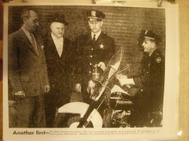
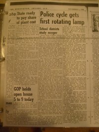

This is what I was referring to. Thanks.Joliet, Illinois The Spectator, November 1, 1956
When it comes to strobes we know that the first beacons looked very similar to aircraft strobes but may have included the addition of a trigger. We don't know if we are right that the aircraft technology was 100% ported over, but I do have some evidence that it was adapted very closely. it looks like the L, K, J, and H remote strobes are pretty much copy overs from the aircraft industry. This style remote strobe appears first in the Darley catalogs along side the other earliest known vehicle strobes and continues on being offered for many years, although becoming less and less a "backbone" product.
Here are my aircraft / runway lights and some info from catalogs about automotive products mirroring them. Also pictured are some bulbs that I have removed from older Whelen and LectricLites beacons.
Early vehicle strobes

Aircraft/runway lights I have


Bulbs I have pulled from older Whelen beacons


Here are some "cross over catalogs" and bulb specs


Bulb reference from 1979 until 1989


1989

This is what I was referring to. Thanks.
When it comes to strobes we know that the first beacons looked very similar to aircraft strobes but may have included the addition of a trigger. We don't know if we are right that the aircraft technology was 100% ported over, but I do have some evidence that it was adapted very closely. it looks like the L, K, J, and H remote strobes are pretty much copy overs from the aircraft industry. This style remote strobe appears first in the Darley catalogs along side the other earliest known vehicle strobes and continues on being offered for many years, although becoming less and less a "backbone" product.
Here are my aircraft / runway lights and some info from catalogs about automotive products mirroring them. Also pictured are some bulbs that I have removed from older Whelen and LectricLites beacons.
Early vehicle strobes
View attachment 236709
Aircraft/runway lights I have
View attachment 236691View attachment 236692View attachment 236693View attachment 236694View attachment 236695
Bulbs I have pulled from older Whelen beacons
View attachment 236701
View attachment 236700View attachment 236699View attachment 236698View attachment 236697View attachment 236696
Here are some "cross over catalogs" and bulb specs
View attachment 236705View attachment 236706View attachment 236707View attachment 236708
Bulb reference from 1979 until 1989
View attachment 236703View attachment 236704
1989
View attachment 236702
Thanks! for all this info, John!
So which Whelen beacon did this tube one come from?

This tube doesn't have a "trigger coil". I don't know of any early Whelen flashlamp that didn't have the trigger coil built in (usually in the base like all other tubes you showed).
Note: the trigger circuit and trigger coil work together to make the flash happen. The trigger circuit charges up a small capacitor with ~200V. When a timing pulse comes in, that cap is shorted to ground (via an SCR or thyristor) which induces a charge delivered to the trigger coil. The trigger coil is a "step-up" transformer which induces a high voltage (thousands of volts but very very low amperage) around the outside of the tube to cause the Xenon to be ionize. In an ionized state, the resistance of the Xenon tube is now lower...thus the primary charge stored in the main caps can now rush through the tube to cause the actual flash to occur.
Here are some tubes I have:

From left to right, tubes 1,2 and 4 were all recovered from Whelen items I got at some point. These three contain a reference to Sylvania part # "R4321A" -- the big tube in the middle is unrelated -- its just a huge Sylvania flash tube to illustrate why Whelen may have turned to Sylvania for tube sourcing (i.e. Sylvania had a serious presence in the market).
The tube all the way on the right is much like yours, John. It bears the letters, "GTC" but I have not yet been able to identify the manufacturer.
The oldest Lectric Lites LL800 I have is ca. 1974 (mentioned earlier). Here's its tube:

It came hand-scratched, "11-74". Also note the tube marking right at the line of the potting, (red dot, same "Gtc" logo).
Thanks! for all this info, John!
So which Whelen beacon did this tube one come from?
View attachment 236713
This tube doesn't have a "trigger coil". I don't know of any early Whelen flashlamp that didn't have the trigger coil built in (usually in the base like all other tubes you showed).
Note: the trigger circuit and trigger coil work together to make the flash happen. The trigger circuit charges up a small capacitor with ~200V. When a timing pulse comes in, that cap is shorted to ground (via an SCR or thyristor) which induces a charge delivered to the trigger coil. The trigger coil is a "step-up" transformer which induces a high voltage (thousands of volts but very very low amperage) around the outside of the tube to cause the Xenon to be ionize. In an ionized state, the resistance of the Xenon tube is now lower...thus the primary charge stored in the main caps can now rush through the tube to cause the actual flash to occur.


92-ST - Edwards Signaling STROBE TUBE
92-ST - Edwards Signaling STROBE TUBE
www.walkerindustrial.com
The odd one came out of a Deitz light, which didn't work with this bulb or a "regular one". I have it in the box I am sending to you. I got a similar Deitz light in the same lot with a "normal bulb" that works fine.
The light that the "triggerless" bulb was in is below.


The one that came with it with a "normal bulb".


Last edited:
Thanks, John -- IIRC, I got a Tripp-lite strobe way back in the day and it used this format (trigger coil buried in the PS). I gather this works fine when the tube is physically very near the PS (specifically the trigger circuit). But when the possibility of that distance was larger, it seemed to become standard practice to put the trigger coil either _in_ the tube, or very close nearby within the fixture itself.View attachment 236716
This one without the trigger coil came out of a Whelen 5000 strobe which was sold as "nonoperating". I replaced it with the more standard bulbs pictured and it fired right up. I assume someone used the wrong replacement bulb. I have seen similar bulbs in an early Deitz strobe I think, I could be wrong. Either way despite not functioning I thought it was odd enough to keep.
I say this with this in mind:

This beacon was a strobe made by "Flash Technology" which would typically be found on radio/tv/comm towers. These would typically be some 300 to 600 feet away from the power supply...but the trigger coil itself would be a component of the light fixture itself.
I went and dug around and revised my statement of where I got the odd bulb... it was out of a Dietz, not sure if it was installed by accident... I detailed it above it looks like an edwards industrial light bulb.Thanks, John -- IIRC, I got a Tripp-lite strobe way back in the day and it used this format (trigger coil buried in the PS). I gather this works fine when the tube is physically very near the PS (specifically the trigger circuit). But when the possibility of that distance was larger, it seemed to become standard practice to put the trigger coil either _in_ the tube, or very close nearby within the fixture itself.
I say this with this in mind:
View attachment 236717
This beacon was a strobe made by "Flash Technology" which would typically be found on radio/tv/comm towers. These would typically be some 300 to 600 feet away from the power supply...but the trigger coil itself would be a component of the light fixture itself.
I added a few more mystery supplies to the lot I'm sending you, I'll repack them at work tomorrow.
Here is a 1970s ad for the glass interior GEN 1 strobe commanderThe only pics, info that I have on the 1000. From 1968 and 1969 Darley catalogs. Then the switch to 1200.

Attachments
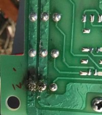
John! You were kind enough to send me this PS to tinker with -- Thanks! -- Here's what I found: The ticking was the repeated arcing across the pins of a compromised outlet port. The inverter would charge up with just enough voltage to allow an arc. That arc would discharge the caps and the process would just repeat (by my sense, about 6 to 8 times a second -- the signature "tick" sound you described).This came in a set of DOT stuff I bought, it was the only non-working one. The capacitor mounts are broken which isn't common, but I don't think that's why it isn't working. It makes a very fast clicking sound when powered up. It was connected to a pair of micro edges with two linear "corner" tubes in each (4 total). Notice there is no "head select" wire, it is either on or off.
I did get a few 94Cs and a UPS64 double flash and a UPS64C comet flash supply in the lot as well as some misc newer stuff, so it was worth it.
View attachment 236581
View attachment 236582
View attachment 236584
View attachment 236583
View attachment 236585
After cleaning up the circuit board around there, re-soldering the pins, and applying some conformal coating, it no longer arcs and with two tubes connected, it works as expected.
I've never seen (more appropriately, "heard") this failure mode before so in case anyone stumbles across this thread chasing a similar symptom, you have something to chase down and rule out at least.
Attachments
I was about to ask for your advice on a problem I experienced with my DMS. This was the last light I used on a VFD and, as you can see, I modified it with a Pyrex tube using red “leaded glass“ dye from a hobby store. Using an xacto knife, I cut Spitfire stripes in it to increase cp output and added 3 died bulbs as tracer lights…probably one of the most effective throw lights I ever used.

The last time I powered it up, the “bulb” on the cb lit up like an over-volted xmas tree light. I immediately powered off in hopes to minimize potential damage. I powered it up this morning to get a photo of the issue, and it is working just fine now! Any thoughts?
Here’s my collection of DMS. The oldest has a different cb. S/No from L to R:
7533; 9588; 11328 (I did the blue tube for my brother who was PD at the time…he preferred my Fireball II)
@dmathieu, ask and you shall receive.
As you can hear, it’s a double flash but the video is too slow to capture:
Red
Blue
As you can hear, it’s a double flash but the video is too slow to capture:
Red
@Maxim2Eng - Those mods are really cool!I was about to ask for your advice on a problem I experienced with my DMS. This was the last light I used on a VFD and, as you can see, I modified it with a Pyrex tube using red “leaded glass“ dye from a hobby store. Using an xacto knife, I cut Spitfire stripes in it to increase cp output and added 3 died bulbs as tracer lights…probably one of the most effective throw lights I ever used.
View attachment 237385
The last time I powered it up, the “bulb” on the cb lit up like an over-volted xmas tree light. I immediately powered off in hopes to minimize potential damage. I powered it up this morning to get a photo of the issue, and it is working just fine now! Any thoughts?
Here’s my collection of DMS. The oldest has a different cb. S/No from L to R:
7533; 9588; 11328 (I did the blue tube for my brother who was PD at the time…he preferred my Fireball II)
View attachment 237387
That neon lamp you point to is meant to turn the inverter off when the cap has charged up according to design.
It is described in this patent and identified in the pic in the patent as "22". Resistor "R7" feeds it....and my guess is R7 might be shorted if you observed it to be unexpectedly bright.
R7 is usually a 470K ohm resistor to it's supposed to just "take a sip" of the cap voltage such that when the neon lamp sees ~80 volts, it turns on...thus sending a signal to Q5 to effectively turn the inverter off.
I had an 800 which had a failure in this part of the circuit. I noticed, "wow! that's a pretty bright flash for an 800!" and noticed a frequent clicking/ticking sound in the cap. That was because it overcharging!
At this point, do you ever see that neon lamp come on? If not, then the transistor it is meant to signal, may now be fried. If so, then the problems are:
1. No overcharge protection for the cap. If the flashtube fails, then cap will be subject to severe overcharging and may fail.
2. No inverter overcurrent sensing. That patent shows how the little current sensing transformer, "T2" shares that part of the signal path. If it has failed, then the main power transistor is subject to extra current which contributes to heat.
I only observed it once years ago when I was organizing my display (~10 years ago). Never tried it since until today. Now is firing normally and no neon light. Is it repairable? Thanks for sharing your expertise (gotta love eLB!).@Maxim2Eng - Those mods are really cool!
That neon lamp you point to is meant to turn the inverter off when the cap has charged up according to design.
It is described in this patent and identified in the pic in the patent as "22". Resistor "R7" feeds it....and my guess is R7 might be shorted if you observed it to be unexpectedly bright.
R7 is usually a 470K ohm resistor to it's supposed to just "take a sip" of the cap voltage such that when the neon lamp sees ~80 volts, it turns on...thus sending a signal to Q5 to effectively turn the inverter off.
I had an 800 which had a failure in this part of the circuit. I noticed, "wow! that's a pretty bright flash for an 800!" and noticed a frequent clicking/ticking sound in the cap. That was because it overcharging!
At this point, do you ever see that neon lamp come on? If not, then the transistor it is meant to signal, may now be fried. If so, then the problems are:
1. No overcharge protection for the cap. If the flashtube fails, then cap will be subject to severe overcharging and may fail.
2. No inverter overcurrent sensing. That patent shows how the little current sensing transformer, "T2" shares that part of the signal path. If it has failed, then the main power transistor is subject to extra current which contributes to heat.
I bought mine from a friend (an outfitter) who had just added Whelen to his inventory. Told him what I wanted to do and he set me up with the clear dome DMS. When I finished, I visited his store to show him the results and the Whelen rep happened to be there…they were blown away. Never made it as a factory option though.Thank you! That is awesome. I have a NOS/NIB same vintage with amber and blue domes. I remember getting one of these when they 1st came out in the early 70s. Thanks again for the videos.
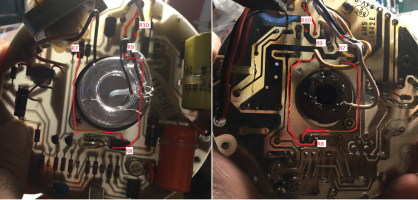
I found this link which describes that a fixed film resistor like R7 is expected to fail only 5% of time in the form of a "short". So now I think it's more likely that there was a break in the path between R8, R9, R10 somewhere. Attached is a pic of the top and bottom of my DMS (same PCB as yours).I only observed it once years ago when I was organizing my display (~10 years ago). Never tried it since until today. Now is firing normally and no neon light. Is it repairable? Thanks for sharing your expertise (gotta love eLB!).
We might be looking at a simple compromised solder joint. In the attached pic, I tried to trace the path along these components as best I could.
The values for the parts (on my DMS) are:
R7 - 470K 1/2 watt
R8 - 100K trimpot
R9 - 100K 1/4 watt
R10- 220K 1/4 watt
If this is the problem, and if I did a little math correctly (pretty big "if"), then the neon lamp and the transistor's emitter may have been exposed to about .85 milliamps. (Ohm's law I=V/R: .85 = 400/470K)...I'm not sure that's enough to cause serious damage.
If this were my unit, this would be my plan:
1. Always observe safety. Never begin any work until verifying CAPS are discharged.
2. Measure across these resistors confirming expected values.
3. Look for any signs of poor soldering both in general, and at specific points along the path shown in red in the attached pic.
4. My DMS is "pegged" to stay in high-power mode (purple power wire is crimped to ground pin of 2-pin power AMP connector - this also effectively takes R10 out of the picture). Because of this, R8 may be tuned such that neon lamp never actually comes on. To create the greatest chance that it would come on under normal conditions, I'd cut the purple power wire (putting it in low-power), and turn the trim pot to it's clock-wise most extreme. I would expect the neon lamp to come on now. If it doesn't then I'd take that to mean the bulb itself is compromised.
Note: I'm not an expert! I'm just another huge fan of these old-school strobes!
Hope this helps!
Attachments
Excellent info, thanks! I can certainly check the board for any obvious issues…the last time I did any PCB work was 50 years ago when I put together an Heathkit tachometer for my IH Scout (4 cylinder). I learned a lot about cold solder….I found this link which describes that a fixed film resistor like R7 is expected to fail only 5% of time in the form of a "short". So now I think it's more likely that there was a break in the path between R8, R9, R10 somewhere. Attached is a pic of the top and bottom of my DMS (same PCB as yours).
We might be looking at a simple compromised solder joint. In the attached pic, I tried to trace the path along these components as best I could.
The values for the parts (on my DMS) are:
R7 - 470K 1/2 watt
R8 - 100K trimpot
R9 - 100K 1/4 watt
R10- 220K 1/4 watt
If this is the problem, and if I did a little math correctly (pretty big "if"), then the neon lamp and the transistor's emitter may have been exposed to about .85 milliamps. (Ohm's law I=V/R: .85 = 400/470K)...I'm not sure that's enough to cause serious damage.
If this were my unit, this would be my plan:
1. Always observe safety. Never begin any work until verifying CAPS are discharged.
2. Measure across these resistors confirming expected values.
3. Look for any signs of poor soldering both in general, and at specific points along the path shown in red in the attached pic.
4. My DMS is "pegged" to stay in high-power mode (purple power wire is crimped to ground pin of 2-pin power AMP connector - this also effectively takes R10 out of the picture). Because of this, R8 may be tuned such that neon lamp never actually comes on. To create the greatest chance that it would come on under normal conditions, I'd cut the purple power wire (putting it in low-power), and turn the trim pot to it's clock-wise most extreme. I would expect the neon lamp to come on now. If it doesn't then I'd take that to mean the bulb itself is compromised.
Note: I'm not an expert! I'm just another huge fan of these old-school strobes!
Hope this helps!
A note about 80's power supply internal model numbers...
Here are few examples of power supply model numbers:
"2A13D11518-41" (8000/5400 series pie-pan ~1980 PCB:"25040F")
"4A13D11518-41" (8000/5400 series pie-pan ~1981 PCB:"65402A")
This number might be stamped onto the assembly, hand-written, or printed on a label placed on the assembly.
I used to think these model numbers were just gobbledygook but now it looks like they may actually convey alot of info in the form of distinct fields - let's add a few more samples and format accordingly and try to make some sense of them:
2A 13 D 115 18 -41 (8000/5400 series pie-plate ~1980 PCB:"25040F")
4A 13 D 115 18 -41 (8000/5400 series pie-plate ~1981 PCB:"65402A")
3A 13 D 90 18 -10 (5200 commander ~1980 PCB:"25040F")
E 21 D 80 15 -10 (1200 ~1982 voltage is dual, labeled "13/26")
1I 13 D 80 08 -10 (800 ~1983) *
5ZD 21 D 80 15 -10 (SS360 ~1992)
B 13 D 115 15 -41 (UPS ~1980 PCB:"25040F")
2B 13 D 115 15 -21 (UPS ~1987 only 2 outlets)
B 13 D 115 15 -39 (UPS ~1983 Indiana Highway Variant PCB:"65459")
ZOM 13/26 Q 140-12 -4BE (UPS-54C ~1994)
Looks like the first field is product/board/revision specific.
Next field is design input voltage.
Then 'D' for double-flash, 'Q' for Comet/Quad, 'S' for single-flash
Then flashes per minute ("RATE____FPM" on the green tag )
Then joules (aka watt-seconds) per main flash ("POWER_____W-SEC" on the green tag)
Then outlet configuration. First digit is number of ports. Not sure what the second digits/letters mean.
*Note that the model 800's joule number is "08" but both samples I have, have a green tag indicating 10 joules/Watt-Seconds.
So lets see what we can tie to the green tag using the UPS Indiana Highway Dept example I have:

Noted in red, are the two components in the part/model number portraying flash rate and joules. "112" isn't quite "115" but close
Noted in yellow are the two components used to calculate joules.
Note the numbers on the capacitors. I suspect Whelen measured each individual capacitor (in micro-farads) at some point, then measured both together connected in series...so we see "221" scratched out on each cap, then one single "111" as the measured capacitance in final tuning/assembly.
(If you're curious about why 111 is about _half_ of 221, google "Capacitor in series" - there are a ton of explanations out there)
Joules are calculated by the formula, J=CV^2/2 ("joules equals capacitance times voltage squared divided by 2") and voltage is normalized in KILO-VOLTS BTW.
So putting it together: 111 X .520 X .520 / 2 = 15.0072
Sure enough, the tag shows "15." as the W-SEC (aka joules).
This model number scheme seemed to only apply from about 1980 through the early '90s.
Of course, if anyone sees anything here that doesn't make sense, please chime in!
Here are few examples of power supply model numbers:
"2A13D11518-41" (8000/5400 series pie-pan ~1980 PCB:"25040F")
"4A13D11518-41" (8000/5400 series pie-pan ~1981 PCB:"65402A")
This number might be stamped onto the assembly, hand-written, or printed on a label placed on the assembly.
I used to think these model numbers were just gobbledygook but now it looks like they may actually convey alot of info in the form of distinct fields - let's add a few more samples and format accordingly and try to make some sense of them:
2A 13 D 115 18 -41 (8000/5400 series pie-plate ~1980 PCB:"25040F")
4A 13 D 115 18 -41 (8000/5400 series pie-plate ~1981 PCB:"65402A")
3A 13 D 90 18 -10 (5200 commander ~1980 PCB:"25040F")
E 21 D 80 15 -10 (1200 ~1982 voltage is dual, labeled "13/26")
1I 13 D 80 08 -10 (800 ~1983) *
5ZD 21 D 80 15 -10 (SS360 ~1992)
B 13 D 115 15 -41 (UPS ~1980 PCB:"25040F")
2B 13 D 115 15 -21 (UPS ~1987 only 2 outlets)
B 13 D 115 15 -39 (UPS ~1983 Indiana Highway Variant PCB:"65459")
ZOM 13/26 Q 140-12 -4BE (UPS-54C ~1994)
Looks like the first field is product/board/revision specific.
Next field is design input voltage.
Then 'D' for double-flash, 'Q' for Comet/Quad, 'S' for single-flash
Then flashes per minute ("RATE____FPM" on the green tag )
Then joules (aka watt-seconds) per main flash ("POWER_____W-SEC" on the green tag)
Then outlet configuration. First digit is number of ports. Not sure what the second digits/letters mean.
*Note that the model 800's joule number is "08" but both samples I have, have a green tag indicating 10 joules/Watt-Seconds.
So lets see what we can tie to the green tag using the UPS Indiana Highway Dept example I have:
Noted in red, are the two components in the part/model number portraying flash rate and joules. "112" isn't quite "115" but close
Noted in yellow are the two components used to calculate joules.
Note the numbers on the capacitors. I suspect Whelen measured each individual capacitor (in micro-farads) at some point, then measured both together connected in series...so we see "221" scratched out on each cap, then one single "111" as the measured capacitance in final tuning/assembly.
(If you're curious about why 111 is about _half_ of 221, google "Capacitor in series" - there are a ton of explanations out there)
Joules are calculated by the formula, J=CV^2/2 ("joules equals capacitance times voltage squared divided by 2") and voltage is normalized in KILO-VOLTS BTW.
So putting it together: 111 X .520 X .520 / 2 = 15.0072
Sure enough, the tag shows "15." as the W-SEC (aka joules).
This model number scheme seemed to only apply from about 1980 through the early '90s.
Of course, if anyone sees anything here that doesn't make sense, please chime in!