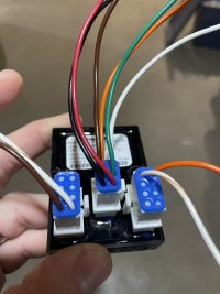
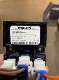
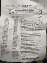
I am looking for some more info on this 2 channel LED flasher I have acquired. It came with a basic install sheet. I have the info on the 6 wires in the power input connector for power, sync, low power, and scan lock.
But what does the brown do on the input connection?
Another question is on the channel out put connections. We have brown and white/brown on channel 1 and orange and white/orange on channel 2. Which is power and which is ground?
Can I populate the other spots on each channel? Essentially giving me 3 connection points on each channel?
The schematic I received from Whelen support shows a max of 5 amps per channel. It’s been 25 years since I took a HS electronics class in tech school. And it looks like it has multiple out puts on each channel, but it all gets internally tied together. Which makes me believe it still maxes out on 5 amps per channel. It does not matter if I populate more pins on each channel connector because they all tie back to a single 5 amp connection internally.
Any help would be thankful.


