So technically, this _is_ an old Whelen power supply! Just not for a strobe ")
Whelen had a portable scene-light product called the "NITEBEAM" -- at this point, the only evidence I can find of this product on the interwebs is the install manual (attached) copyrighted 1998.
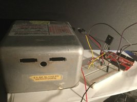
I got a hold of an original Whelen power-supply (part listed on eBay) and hooked it up to a 70-watt metal-halide bulb and it works as expected.
This power supply has to:
1. Supply a relatively high voltage, low-current output to the bulb to initiate the arc (just like a conventional Xenon flash tube)
2. Once the arc is established, resistance is low. The PS must now kill the high-voltage output and feed a relatively low-voltage, current-limited output to sustain the arc, let the tube warm up, then:
3. Maintain the current limit and keep the lamp running.
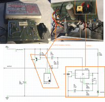
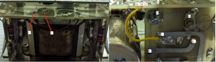
Because the PS is potted, I 'm unable to examine the circuitry but I have I suspect what Whelen learned and applied to their strobe PSs (w/r/t sensing flashtube firing, and sensing current through the primary coil of the inverter), was applied to this PS with a different purpose in mind.
I gather the product itself didn't sell terribly well...but I think it was cool and interesting none the less.
Here's a vid of it starting up, running, and being turned off:
https://youtu.be/SX-3cHEIyTA
Whelen had a portable scene-light product called the "NITEBEAM" -- at this point, the only evidence I can find of this product on the interwebs is the install manual (attached) copyrighted 1998.
I got a hold of an original Whelen power-supply (part listed on eBay) and hooked it up to a 70-watt metal-halide bulb and it works as expected.
This power supply has to:
1. Supply a relatively high voltage, low-current output to the bulb to initiate the arc (just like a conventional Xenon flash tube)
2. Once the arc is established, resistance is low. The PS must now kill the high-voltage output and feed a relatively low-voltage, current-limited output to sustain the arc, let the tube warm up, then:
3. Maintain the current limit and keep the lamp running.
Because the PS is potted, I 'm unable to examine the circuitry but I have I suspect what Whelen learned and applied to their strobe PSs (w/r/t sensing flashtube firing, and sensing current through the primary coil of the inverter), was applied to this PS with a different purpose in mind.
I gather the product itself didn't sell terribly well...but I think it was cool and interesting none the less.
Here's a vid of it starting up, running, and being turned off:
https://youtu.be/SX-3cHEIyTA